
US 254798
UNITED STATES PATENT OFFICE.
GEORGE W. CILLEY, OF NORWICE, CONNECTICUT.
REVOLVING FIRE-ARM.
SPECIFICATION forming part of Letters Patent No. 254,798, dated March 14, 1882.
Application filed December 30, 1881. (No model.)
To all whom it may concern:
Be it known that I, George W. Cilley, a citizen of the United States, residing at Norwich, in the county of New London and State 5 of Connecticut, have invented a new and useful Improvement in Locks for Fire-Arms, of which the following is a specification.
My invention relates to that class of firearms, known as “double-acting revolvers,” in which the hammer may be drawn back to fullcock by the use of the trigger alone, although it cannot be set at full-cock by this means, and in which one spring serves to operate the hammer, the trigger, and the revolver-lever, the object being to simplify the construction and to lessen friction. I attain these objects by the mechanism illustrated in the accompanying drawings, in which—
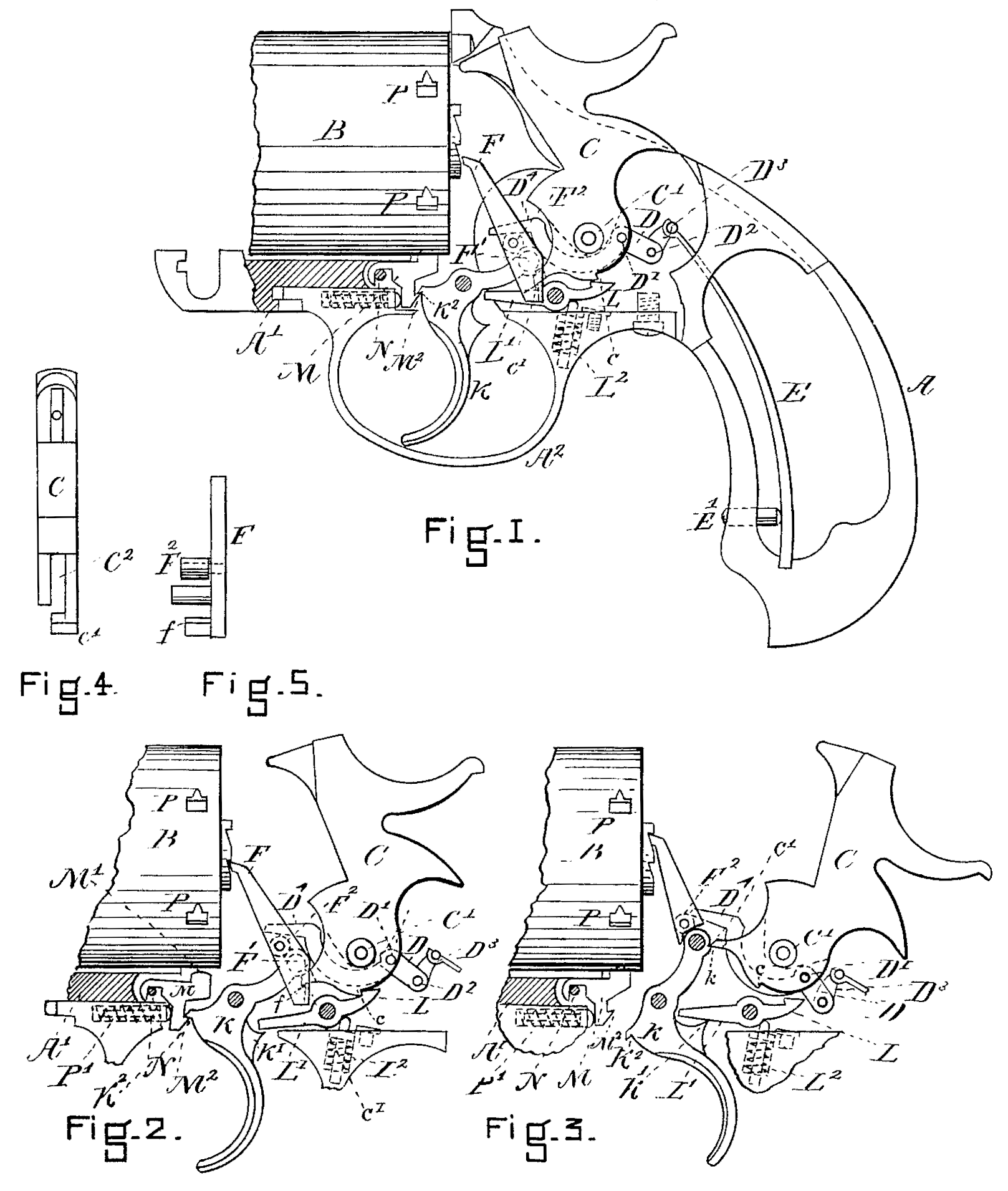
Figure 1 is a longitudinal view, part in elevation and part in section. Fig. 2 is a detail in elevation showing the moving parts at halfcock. Fig. 3 is a detail in elevation showing the moving parts at full-cock. Fig. 4 is a front elevation of the hammer. Fig. 5 is a front elevation of the revolver-lever.
A. A¹ represent the stock, and A² the trigger guard; B, the revolver-chamber— all of which parts may be made in any of the usual modes.
The hammer C is provided with a half-cock point, c, and a full-cock point, c¹, and is hung upon a pivot, C¹. The lower portion of the hammer C is made with a recess, C², which divides it into two parts, as shown in Fig. 4. This recess C² makes a place for the sickle-lever D, the said lever D being pivoted to the hammer C at D¹. This lever D has a limited motion within the hammer. Attached to the end of the sickle-lever D by a pivot, D², is a link, D³, which serves to connect the lever to the spring E. This spring E, acting through the link D³ and lever D, serves to operate the hammer C. It also, through the same means, operates the revolver lever or pawl F, and, as the revolver lever F is pivoted at F¹ to the trigger K, it also operates the trigger. The tension of the spring E may be adjusted by the screw E¹.
To lessen the friction of the end D⁴ of the lever D in its action on the lever F, I insert a friction-roll at F², which is connected to the lever F by a pin or stud passing through it.
L L¹ is a pawl-lever or sear for holding the hammer at half-cock, as shown in Fig. 2.
L² is a spring-piston, which acts upon the sear L L¹ and throws it into the position shown in Fig. 2, and there holds it until the movement of the trigger K, operating at the point K¹, throws and holds it out. (See Fig. 3.)
M is a stop, located in a recess made in the stock, and placed immediately under the end of the revolving chamber B, and is provided with a detent, M¹, which enters the notches P in the chamber B and holds the said chamber in position, as shown in Fig. 1. This stop M swings and slides on a pivot, N, and is provided with a notch and an inclination at M². The trigger K has a notch at K², which engages with the corresponding notch, M², on the stop M, so that at the beginning of the motion of the trigger K the stop M is drawn downward, as indicated in Fig. 2, and is there held while the hammer is at half-cock, in which position the stop Mallows of the free movement of the chamber B. When the trigger is pulled farther back, as shown in Fig. 3, the notches M² K² separate, and the stop M flies back into position. This latter motion of the stop M is caused by the spring-piston P¹. The stop M is pivoted loosely on the pivot N to admit of its being pushed backward by the notch K² at the return of the trigger K, so as to allow the notch K² to resume its position of engagement with the notch M², as shown at Fig. 1.
To half-cock my lock the hammer C is brought back to the position shown in Fig. 2, in which position the revolver may be loaded. To set at full-cock and ready for firing, the hammer may be drawn back to the position represented in Fig. 3, in which case the notch k at the upper end of the trigger K will hold the hammer by the point c¹, as shown in Fig. 3, until the trigger is moved, which action will allow the hammer to move forward and explode the charge. At the same time the lever D, acting through its end D⁴, will throw down the revolver-lever F from the position shown in Fig. 3 to the position shown in Fig. 1.
For occasions when rest at full-cock is not practicable the hammer C may be made to perform its function by operating the trigger K, the operation being to draw the lower end of the trigger backward, which will cause the upper end to move upward, taking with it the revolver-lever F, anti as the point c of the hammer rests on the projection f, attached to the lever F, (see Figs. 2 and 5,) it—the hammer— is thrown back about the same as at full-cock, in which position the projection f passes out of engagement with the point c¹ and allows the hammer to fly back and discharge the pistol.
Having thus set forth my invention, what I claim, and desire to secure by Letters Patent, is—
1. The combination of the spring E, its connecting-link D³, the sickle-lever D D⁴, having a cross-axis, D¹, with the revolver-lever F, having a friction-stud, F², all operating together substantially as described, and for the purpose set forth.
2. The combination of the trigger K, having a notch, K², with the stop-piece M M¹, having a notch at N, whereby it is allowed to move back and forth, all arranged substantially as described, and for the purpose set forth.
GEORGE W. CILLEY.
Witnesses:
Frank G. Parker,
R. L. Fuller.