
US 361100
UNITED STATES PATENT OFFICE.
DANIEL B. WESSON, OF SPRINGFIELD, MASSACHUSETTS.
LOCK DEVICE FOR FIRE-ARMS.
SPECIFICATION forming part of Letters Patent No. 361,100, dated April 12, 1887.
Application filed August 4, 1886. Serial No. 209,993. (No model.)
To all whom it may concern:
Be it known that I, DANIEL B. WESSON, a citizen of the United States, residing at Springfield, in the county of Hampden and State of Massachusetts, have invented new and useful Improvements in Lock Devices for Fire-Arms, of which the following is a specification.
This invention relates to improvements in lock devices for fire-arms, the object being to provide improved self cocking and firing trigger mechanism therefor, said improvements being applicable to arms provided with either concealed or visible hammers; and the invention consists in the peculiar construction and arrangement of the lock devices and guard of the arm, all as hereinafter fully described, and set forth in the claims.
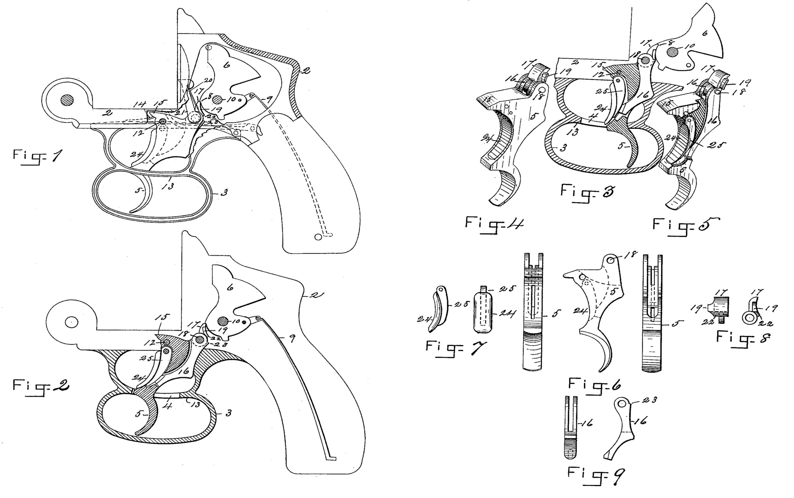
In the drawings forming part of this specification, Figure 1 is a side elevation, partly in section, of that part of a fire-arm containing the lock mechanism embodying my invention. Fig. 2 is a similar view to Fig. 1, but showing the guard of the arm and the cocking-trigger in section. Fig. 3 illustrates the position of the cocking-trigger and the firing-trigger when the hammer is brought to full-cock and is brought under the control of the latter-named trigger. Fig. 4 is a perspective view of the firing and cocking trigger in the condition in which they are placed in the arm. Fig. 5 is a similar view to Fig. 4, but showing the side of the firing-trigger broken away. Fig. 6 illustrates the firing-trigger in front and rear and in side elevations. Fig. 7 illustrates the firing trigger in side and in front elevation. Fig. 8 shows a front and a side elevation of the sear. Fig. 9 shows a side and an edge elevation of the sear-lever.
In the drawings, 2 indicates the frame part of the fire-arm, in which are located the lock devices of the latter, and to the under side of which the guard 3 is secured; but in this construction said guard is made with a double loop to provide means for the separate and independent action of two of the fingers of the hand on the triggers when the arm is fired, as below described, the said guard having a longitudinal slot, 4, through its central rib, between its two loops, in which the cocking-trigger 5 swings. The hammer 6 is of the ordinary type, and is illustrated in what is termed a “concealed-hammer arm,” and is provided with the usual sear-notch, 8, and is attached to the ordinary mainspring, 9, in the usual way, and swings on the pivot 10.
The below-described cocking and firing triggers, together with their peculiar sear and sear-lever construction, provide great advantages in concealed-hammer pistols and other similar arms, with or without such hammers, in that they permit the hammer to be brought to a full-cock, and then to be fired by a free finger of the hand while the hammer is held cocked by another finger, thus permitting the arm to be manipulated more delicately and fired with much more accuracy.
The cocking-trigger 5 is pivoted at 12 in the frame of the arm, and its lower end extends downward through the upper loop of the guard 3, passes through the slot 4 in the central rib, 13, and its lower end hangs in the lower loop of the guard, as shown. A spring, 14, engages under a projection, 15, on said trigger, to swing the latter to the position shown in Fig. 1, or that which is required preparatory to firing the arm. Said cocking-trigger is chambered between its sides, as shown in Figs. 2 and 3, where it is shown in longitudinal section in Fig. 6, where its front and rear edges are shown, and in Fig. 5, in which one side is broken away. The chamber in said trigger is provided for the reception of the sear-lever 16, which, together with the sear17, is pivoted in the upper end of said trigger at 18, the joint part of said sear entering between the bifurcated ends of the sear-lever, and being capable, as below described, of swinging independently of and in conjunction with said sear-lever in the act of cocking and firing the arm.
A laterally-projecting lip, 19, on the sear 17 affords a bearing for one end of a spring, 20, which is secured by its other end to the pawl 21, which acts to rotate the cylinder of the arm, said pawl having a suitable connection with the upper end of the trigger 5, as shown in Fig. 1. Spring 20 serves both to swing the upper end of said pawl outward toward said cylinder (not shown in the drawings) and to swing the free end of the sear against the hammer and cause it to engage with the sear-notch 8 thereon.
The sear 17 and the sear-lever 16, respectively, are each provided with a shoulder, 22 and 23, which shoulders are brought together when, after the sear has become engaged with the sear-notch of the hammer, the cocking-trigger 5 is in the act of cocking the arm swung from the position shown in Figs. 1 and 2 to that shown in Fig. 3,and when said shoulders are in conjunction the sear is brought under the control of the trigger-lever 16.
The firing-trigger 24 has a curved face, as shown, and a rearwardly-projecting lip, 25, and is pivoted by its upper end in the cocking trigger 5, as shown, and its lip 25 enters the chamber in the last-named trigger and terminates directly before the lower end of the trigger-lever 16.
The operation of my improvements is as follows: When the arm is to be fired, the arm is held by placing (preferably) the first and second fingers of the hand respectively through the upper and the lower loops of the guard 3, thus bringing the second finger against the tail of the cocking-trigger and the first finger to such a position before the firing-trigger as enables the operator to operate the latter at will. The cocking-trigger is then pulled, swinging its lower end rearwardly and bringing it to a stop against the end of the slot 4in the guard, and thereby the hammer is brought to a cocked position, as in Fig. 3, the sear 17 swinging on the pivot 18 and maintaining its engagement with the hammer while the latter swings, and when, or shortly before, it comes to a full-cock the shoulders 23 and 22 of the sear and sear-lever meet, causing the lower end of the latter to swing against the edge of the lip 25 on the firing-trigger 24, swinging the lower end of the latter outward slightly from the cocking-trigger to the position shown in Fig. 3, and then, with the said first finger of the hand, the firing-trigger is pressed, swinging rearwardly the tail of lever 16 and throwing the end of the sear out of the sear-notch on the hammer, letting the latter swing and fire the arm. After firing, trigger 5 is released and the spring 14 returns the parts to the positions shown in Fig. 1, and said operations may be repeated. Thus it is seen that in the act of firing, as above described, when the cocking-trigger is pulled the sear at first swings independently of and finally in conjunction with the sear-lever, bringing the latter and the firing-trigger into such delicate lever relation that the arm is fired with a very light trigger-pull, which is all-important when accuracy of aim is desired.
What I claim as my invention is—
1. Improved lock devices for fire-arms, consisting of the cocking-trigger pivoted in the frame of the arm, the sear and the sear-lever, having a common pivotal connection on said trigger, said sear having a swinging movement independently of said lever and in conjunction therewith, combined with the firing-trigger pivoted in the cocking-trigger and engaging with said lever, and the hammer, substantially as set forth.
2. The cocking- trigger, the sear and the sear-lever pivoted on said trigger and having a co-engagement one with the other, the firing-trigger pivoted on and swinging independently of the cocking-trigger and engaging with said lever, combined with a hammer concealed in the frame of the arm, substantially as set forth.
3. A guard for fire-arms having two loops separated by a longitudinally-slotted rib, combined with the cocking-lever pivoted in the frame of the arm and passing transversely through said two loops and slot, and having a vibratory motion therein, and terminating in the lower loop of the guard, and the firing-trigger pivoted in the cocking-trigger within the upper loop of said guard, substantially as set forth.
4. The cocking-trigger capable of a vibratory motion in the frame of the arm, the sear and the sear-lever pivoted on said trigger at the same point,and provided each with a shoulder for engagement with each other, combined with the firing-trigger, the hammer, and a spring to swing said sear toward the latter, substantially as set forth.
DANIEL B. WESSON.
Witnesses:
WM. H. CHAPIN,
G. M. CHAMBERLAIN.