
US 566399
UNITED STATES PATENT OFFICE.
IVER JOHNSON AND ANDREW FYRBERG, OF WORCESTER, MASSACHUSETTS; SAID FYRBERG ASSIGNOR TO SAID JOHNSON.
LATCH FOR RETAINING CYLINDERS ON SPINDLES.
SPECIFICATION forming part of Letters Patent No. 566,399, dated August 25, 1896.
Application filed July 14, 1890. Serial No, 358,724, (No model.)
To all whom it may concern:
Be it known that we, IVER JOHNSON and ANDREW FYRBERG, citizens of the United States, and residents of Worcester, in the county of Worcester and State of Massachusetts, have invented a new and useful Improvement in Revolving Firearms, of which the following is a specification, reference being had to the accompanying drawings, representing such portions of a revolving firearm as embody our invention, and in which—
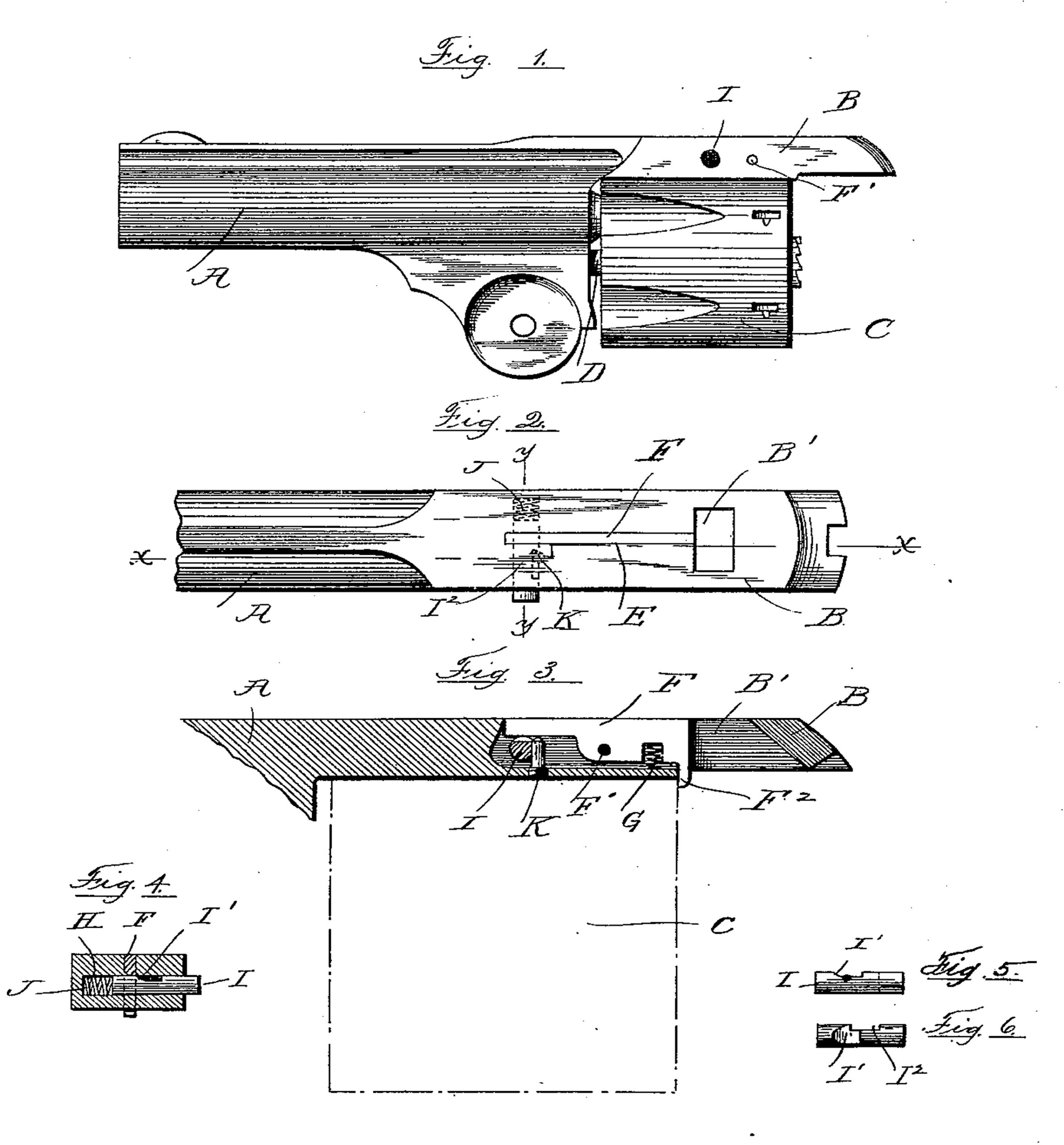
Figure 1 denotes the barrel and revolving cartridge-holding cylinder. Fig. 2 is a view of the barrel-strap shown in top view. Fig. 3 is a sectional view of the barrel-strap on line X X, Fig. 2. Fig. 4 is a cross-sectional view of the barrel-strap on line Y Y, Fig. 2; and Figs. 5 and 6 represent detached views of the sliding pin.
The object of our invention is to provide means for locking the revolving cartridge-holding cylinder in place and retain it upon its supporting-spindle, and in the accompanying drawings we have represented the portion of a revolving firearm shown in Fig. 1 full size and the portions represented in the remaining figures as enlarged twice their size. A denotes the barrel, and B the barrel-strap extending from the barrel over the cartridge-holding cylinder C and provided with a mortise B’ to receive the upper end of the post (not shown) in the usual manner in firearms of this class.
C denotes the cylinder, capable of being rotated upon a spindle D in order to bring its chambers successively in alinement with the barrel. When the cylinder C has been placed in position upon the spindle D, it is held by a latching device, which forms the subject of our present invention, and which is shown in detail in the accompanying drawings. The barrel-strap C is provided with a longitudinal mortise E, in which is placed the latch F, turning upon a pivotal pin F’, held in the body of the strap C. The latch F is provided with a prong F2, which projects below the lower surface of the barrel-strap next the cylinder C, and serves to retain the cylinder upon the spindle D. Between the pivotal pin F’ and the prong F2 a spring G is placed, held in a chamber in the barrel-strap and having its tension applied to the pivoted latch F to raise the prong F2 and release the cylinder C.
H is a transverse chamber in the barrel-strap C, in which is placed a sliding pin I, provided with a cam-surface at I’, so shaped that the outward-sliding motion of the pin will serve to raise the end of the latch F and carry the prong F2 below the lower surface of the barrel-strap into the position shown in Fig. 3. The sliding pin I is forced outward by a spring J, held in the chamber H, and the motion of the pin is limited by a pin K, held in the barrel-strap and placed in the path of the shoulder I2 in the sliding pin I.
The tension of the spring J is greater than the tension of the spring G, and as the sliding pin I is forced outward the cam-surface I’ will rock the latch upon its pivot and carry the prong F2 below the under surface of the barrel-strap, in position to engage the end of the cylinder C. (Indicated in Fig.3 by broken lines.)
When it is desired to release the cylinder C, the sliding pin I is pushed in, compressing the spring J and carrying the cam-surface I’ out of contact with the latch F, allowing the spring G to raise the prong F2 and release the cylinder C.
We are aware that a pivoted latch held in the barrel-strap and provided with a notch or hook to engage the rear end of the cylinder and retain it upon its spindle has been heretofore used, and we do not herein claim such, broadly, as our invention.
What we claim as our invention, and desire to secure by Letters Patent, is—
The combination with the barrel-strap provided with a longitudinal mortise, of a rigid latch F pivoted midway its length and provided at its rear end with the prong F2 projecting below the barrel-strap and adapted to engage the end of the cylinder, a spring G applied to said latch between the prong and pivot to raise the prong and release the cylinder, a sliding pin placed transversely to said latch and provided with a cam-surface acting against said latch at its forward end and on the opposite side of the pivot to the spring G, a spring J acting against said sliding pin to move its cam-surface beneath the latch and depress the prong F2 against the tension of the spring G and a stop-pin arranged to engage said sliding pin and limit its movement by said spring J, substantially as described.
Dated at Worcester, in the county of Worcester and State of Massachusetts this 16th day of June, 1890.
IVER JOHNSON,
ANDREW FYRBERG.
Witnesses:
RUFUS B. FOWLER,
H. W. FOWLER.