
US 465179
UNITED STATES. PATENT OFFICE.
IVER JOHNSON AND ANDREW FYRBERG, OF WORCESTER, MASSACHUSETTS;
SAID FYRBERG ASSIGNOR TO SAID JOHNSON.
REVOLVER.
SPECIFICATION forming part of Letters Patent No. 465,179, dated December 15, 1891.
Application filed March 12,1889. Serial No. 303,036. (No model.)
To all whom it may concern:
Be it known that we, IVER JOHNSON and ANDREW FYRBERG, citizens, of the United States, and residents of Worcester, in the county of Worcester and State of Massachusetts, have invented a new and useful Improvement in Fire-Arms, of which the following is a specification, reference being had to the accompanying drawings, forming a part of the same, in which—
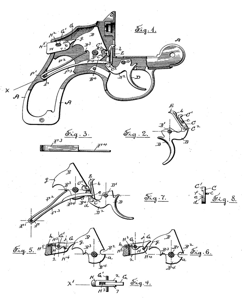
Figure 1 represents the frame of a revolving fire-arm, shown partly in section, and also exhibiting a portion of the lock mechanism. Fig. 2 is a detached view.of the trigger with the pawls for actuating the cylinder and hammer pivoted thereto. Fig. 3 is a sectional view of the mainspring on line X, Fig.1. Fig. 4 is a detached and top view of the mechanism for locking the hammer against cocking. Fig. 5 is a detached view of the hammer with the hammer-locking mechanism shown in sectional view on line X’, Fig. 4. Fig. 6 represents the same parts as are shown in Fig. 5, but with the hammer-locking mechanism in a different position, allowing the hammer to be cocked. Fig.7 represents a modified form of the portion of the lock shown in Fig. 1, and Fig.8 is a detached view of the hammer-actuating pawl.
Similar letters refer to similar parts in the different figures.
Our invention relates to the lock mechanism of fire-arms; and it has for its objects to so arrange the operating parts that the hammer shall be actuated in the operation of tiring and the hammer-cocking mechanism connected with the trigger shall be reversed by the force of the mainspring; and, further, to securely lock the hammer from being inadvertently cocked.
In the accompanying drawings, A denotes the frame of the fire-arm, a portion having been removed in order to disclose the lock mechanism, only such portions of the lock mechanism being shown as are concerned in our present invention.
B denotes the hammer, pivoted at B’ and provided with a notch: B2, which is engaged by the projecting lip C’ of the pawl or “raiser” C, which is pivoted at C2 to the trigger D. The trigger D is pivoted to the frame at D’, and to the wing D2 is pivoted the pawl C, by which the hammer is actuated in the operation of cocking, and also the pawl E, by which the cylinder is rotated in the usual and well known manner.
The mainspring F is preferably formed in a single piece, connected to the frame A by a pin F’ and having the two leaves F2 F3. The leaf F2 bears with its free end against the shoulder B3 of the hammer B, and the leaf F3 is provided at its free end with the blade F4, arranged in a vertical plane and resting upon the wing D2 of the trigger D. The tension of the mainspring F is thereby applied to force the hammer forward against the firing-pin, and also to move the wing D2 downward and carry the trigger forward by the action of the leaves F2 F3.
As the trigger D is brought back in the operation of cocking the hammer, it is rotated
about the pivot D’, lifting the pawl C, and by means of the engagement of the lip C’ with the notch B2 the hammer is rotated about its pivot B’, the action of the trigger and hammer, as described, bringing the leaves F2 F3 of the mainspring F closer together until the face a of the tumbler B2 of the hammer is brought against the side of the pawl C, forcing the lip C’ out of the notch B2 and allowing the tension of the mainspring F, exerted through the leaf F2, against the shoulder B3 of the hammer to carry the hammer violently against the firing-pin in the usual manner. As the trigger is released, the leaf F3 of the mainspring serves to carry the trigger forward into its normal position.
In the construction shown in Fig. 1 the pawl C is held against the hammer by means of a small spring b, in the present instance attached to the pawl E and acting against the pin c in the pawl C. The two pawls are thereby thrown apart, the pawl C being held against the hammer and the pawl E being pressed forward to engage the ratchet-teeth upon the cylinder, which have not been shown in the drawings, as the action of the cylinder-pawl forms no part of our present invention.
In the case of fire-arms other than revolving the cylinder-pawl is not required and the joint action of the spring b can be dispensed with. We actuate the hammer-pawl, as well as the trigger, in such cases by means of the leaf F3 of the mainspring F, by means of the construction shown in Figs. 7 and 8 of the drawings. The pawl C is provided with a shoulder d, Fig. 8, having an inclined wall e, forming the point f, upon which the blade F4 of the leaf F3 of the mainspring rests. As the point f is at the left of a vertical line drawn through the center of the pivot C2, Fig. 7,it is obvious that the downward pressure of the leaf F3 upon the point f will not only serve to carry the trigger forward, as has already been described, but will also act to rotate the pawl C upon its pivot C2 and hold the upper end of the pawl against the hammer, causing the lip C’ to engage the notch B2 in the hammer B. Although the mainspring F, as shown, is preferably made in a single piece, the action of the two leaves F2 and F3 is independent, and the leaves can be made in separate pieces and attached to the frame A, if desired. The hammer is locked against the action of cocking by means of the device shown in Fig. 1 and in detail in Figs. 4, 5, and 6.
The hammer B is provided with a shoulder g, which is engaged by the latch G, pivoted upon a pivotal pin G’, held in the frame A, as shown in Fig. 4 and in section in Figs. 1, 5, and 6. The pivoted end of the latch G is inclosed by the sides 1 and 2 of the bifurcated sliding block H, which projects through the frame A, mortised at H’ for the purpose, and slides upon the pin G’, which passes through a slot H2. A spiral spring H3 is inserted in the block H, its ends resting against the wall h of the block H, and the pivoted end of the latch G serving to press the sliding block H away from the end of the latch H and in the positions shown in Figs. 1 and 5. The latch G has an inclined or cam surface at j, and the sides of the block H carry a pin H4 in contact with the inclined surface of the latch. In the normal position of the several parts, as shown in Figs. 1 and 5, the latch is made to rest upon the pin H4, holding the free end of the latch in position to engage the shoulder g of the hammer and prevent the rotation of the hammer in the operation of cocking. By pressing against the projecting end H5 the sliding block H is moved forward, compressing the spiral spring H3 and sliding the pin H4 over the inclined surface j, thereby raising the free end of the latch G so it will clear the shoulder g of the hammer, allowing it to be cocked. The position of the several parts of the hammer-locking device as assumed when the sliding block H has been pushed in is shown in Fig. 5, in which the pin H4, carried by the sliding block H, is shown as having moved across the inclined surface j and raised the free end of the latch G to allow the hammer to be moved. The sliding motion of the block H is limited by the slot H2, thereby limiting the movement of the pin H3 to the traverse of the inclined surface j of the latch G. The spring H3 is applied to the end of the latch G at a point above the center of the pivotal pin G’, so that the tension of the spring H3 not only serves to press the sliding block H outward and away from the pivoted end of the latch G, but also to rotate the latch upon its pivotal pin G’ and carry the free end of the latch downward in position to engage the shoulder g of the hammer B, in which position it is supported by the pin H4.
We are aware that it is not new to lock the hammer of fire-arms from movement.in the action of cocking. Such we do not claim, broadly.
What we do claim, and desire to secure by Letters Patent, is—
1. The combination, with the hammer of a fire-arm, of a retaining-latch pivoted to the rigid portion of the fire-arm and arranged to engage said hammer and prevent its being cocked, said retaining-latch having an inclined or cam surface, and a movable piece arranged to act against the inclined or cam surface of said retaining-latch and move said latch out of the path of the hammer, substantially as described.
2. The combination, with the hammer of a fire-arm, of a retaining -latch pivoted to the rigid portion of the fire-arm, a spring with its tension applied to said latch to carry it into and hold it in the path of the hammer as said hammer is moved in the operation of cocking, whereby said hammer is securely locked against cocking, an inclined or cam surface upon said: retaining-latch, and a movable piece arranged to act against said inclined or cam surface and move the retaining-latch out of the path of the hammer, substantially as described.
3. The combination, with the hammer of a fire-arm, of a retaining-latch pivoted in the rigid portion of the fire-arm and arranged to engage said hammer and prevent its being cocked, said latch having an inclined or cam surface, a movable piece arranged to be moved against and be made to act upon said inclined surface of the retaining-latch and move said latch out of the path of the hammer, and a
spring with its tension applied to said movable latch-actuating piece and reverse its movement, substantially as described.
4. The combination, with the hammer of a fire-arm, of a retaining-latch by which said hammer is held from being cocked, an inclined or cam surface on said latch, a sliding piece arranged to be moved against and act on said inclined surface of the retaining-latch and move it out of the path of the hammer, and a spring with its tension applied jointly to said latch to carry it.into the path of the hammer and.also to said sliding piece to reverse its motion and carry it away from the inclined or cam surface of said latch, substantially as described.
5. The combination, with the hammer of a fire-arm, provided with a shoulder to receive a retaining-latch, of a retaining-latch pivoted at one end to the rigid portion of the frame of the fire-arm, an inclined or cam surface on said retaining-latch, a sliding piece acting against said inclined surface to move the retaining-latch out of the path of the hammer, and a spring with its tension applied to said latch to rotate it on its pivot and bring its free end into the path of said hammer and also to said sliding piece to reverse its motion and carry it away from the cam-surface upon said latch, substantially as described.
6. The combination, with the hammer of a fire-arm, provided with a shoulder, of.a retaining-latch pivoted at one end to the frame of the fire-arm and with its free end arranged to engage the shoulder upon said hammer and prevent its being cocked, an inclined or cam surface on said latch, a bifurcated sliding block inclosing the pivoted end of said retaining-latch and provided with a slot through which the pivot of the latch passes and by which the sliding motion of the block is limited, a pin carried by said sliding block and in position to act upon the inclined surface of the retaining-latch as the block is moved, and a spring placed between the pivoted end of said latch and said sliding block so its tension will act jointly upon said block and latch to carry the latch around its pivot and bring its free end in position to engage the shoulder
upon the hammer and also to reverse the motion of said sliding block, substantially as described.
7. In the lock mechanism of a fire-arm, the combination, with a pivoted hammer having a notch to receive an actuating-pawl, of a pivoted trigger carrying a hammer-actuating pawl pivoted thereto, with its free end engaging said notch in the hammer, and a spring with its ends approaching each other and hayving one end engaging the rear of the hammer to actuate the same in the operation of discharging the fire-arm and the other end of the spring applied to reverse the motion of the trigger after the discharge of the fire-arm, substantially as described.
8. The combination of a pivoted hammer provided with a notch to receive an actuating-pawl and a shoulder to receive the force of the hammer-actuating spring, a hammer-actuating spring held by the frame-work and bearing against the shoulder upon the hammer to effect the discharge of the fire-arm, a pivoted trigger carrying a hammer-actuating pawl, a hammer-actuating pawl pivoted on said trigger with its free end engaging the notch in the hammer and provided with a shoulder, and a spring held in the frame-work and bearing against said shoulder to rotate the pawl and bring its free end into engagement with the notch in the hammer, substantially as described.
9. The combination of a pivoted hammer provided with a notch to receive an actuating-pawl and having a projection arranged to be brought against the hammer-actuating pawl and disengage the same as the hammer is cocked, a pivoted trigger, a hammer-actuating pawl pivoted on said trigger with its free end engaging the notch in the hammer and provided with a projecting shoulder, a spring held in the frame with its free end applied to said trigger to reverse its motion after the discharge of the fire-arm, a pawl pivoted on said trigger to actuate the cylinder of the fire-arm, and a spring with one end connected with said cylinder-actuating pawl and with its opposite end connected with said hammer-actuating pawl, so its tension will be applied jointly to said pawls to bring them into engagement with the hammer and with the cylinder, substantially as described.
10. The combination, with a pivoted hammer having a notch to receive an actuating pawl, of a pivoted trigger, an actuating-pawl pivoted to said trigger and engaging the notch in said hammer, a projecting shoulder at the side of said pawl and preferably forming a portion thereof, having an inclined surface terminating in a point upon which the tension of a spring is applied to hold said pawl in engagement with said hammer, and a spring with its tension applied to said shoulder and, through the pivoted connection of said pawl with the trigger, serving to reverse the motion of the trigger, substantially as described.
IVER JOHNSON,
ANDREW FYRBERG.
Witnesses:
RUFUS B. FOWLER,
H. M. FOWLER.