
US 371532
UNITED STATES PATENT OFFICE.
DANIEL B. WESSON, OF SPRINGFIELD, MASSACHUSETTS.
REVOLVING FIRE-ARM.
SPECIFICATION forming part of Letters Patent No. 371,532, dated October 11, 1887.
Application filed March 28, 1887. Serial No. 232,702. (No model.)
To all whom it may concern:
Be it known that I, DANIEL B. WESSON, a citizen of the United States, residing at Springfield, in the county of Hampden and State of Massachusetts, have invented new and useful Improvements in Revolving Fire-Arms, of which the following is a specification.
This invention relates to revolving fire-arms and pertains to improvements in barrel-catch mechanism therefor; and the invention consists in the peculiar construction and arrangement of the parts of the above-referred-to mechanisms, all as hereinafter fully described, and pointed out in the claims.
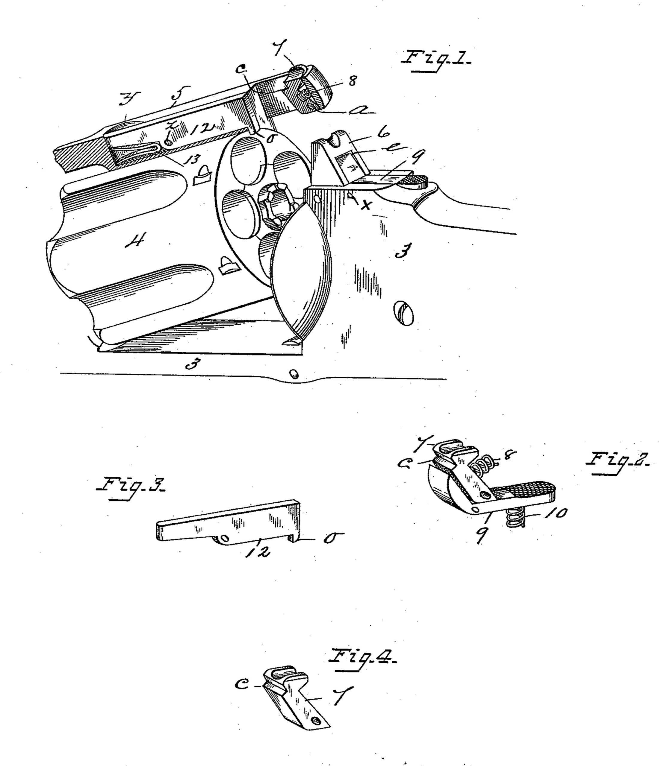
In the drawings forming part of this specification, Figure 1 is a perspective view of a portion of the frame and the cylinder of a revolving fire-arm and the barrel-strap thereof, (the latter being in longitudinal section,) having applied thereto barrel-catch mechanism embodying my improvements. Figs. 2 and 4 are perspective views of detail parts of said mechanism, hereinafter fully described. Fig. 3 is a perspective view of the cylinder-catch.
In the drawings, 3 indicates the frame of the arm, to which the barrel is hinged in the usual manner, the cylinder 4 having the well-known rotary connection with the barrel, and the latter being provided with the strap 5, which extends longitudinally over the cylinder in order to engage with the frame 3 back of the latter and form a connection between the barrel and frame above the cylinder.
In the drawings the strap 5 is represented as broken off from the barrel, no part of the latter being shown, as the invention herein described pertains to devices connected directly with said barrel-strap and with the frame of the arm directly back of the cylinder.
One of the main objects of the improved barrel-catch devices herein described is to provide such a construction thereof and to so arrange their operative parts as to bring the latter within convenient reach of the thumb of the hand which grasps the handle of the arm, in order that the latter may, while held by the hand after firing it, be thrown open to eject the empty shells and bring the cylinder into proper position for reloading, thereby providing for said manipulation by the use of one hand only, and at the same time securing a symmetrical construction and adaptation of said devices.
In carrying out my invention relative to the aforesaid barrel-catch mechanism, the end of the barrel-strap 5 is perforated, as shown, whereby an opening through it is formed large enough to allow the end of the catch post 6 on the frame 8 to pass through it and to pivotally attach a dog, 7,within said opening. The said dog is pivoted in the barrel strap at a, and between the dog and the adjoining end of said opening is placed a spring, 8, and the dog is capable of a limited vibratory motion within said opening. The outer face of the dog has formed thereon a tooth, c, which is adapted to engage with the upper end of a slot, e, in the rear side of the catch-post 6, which constitutes a catch-notch for said dog when the barrel-strap is swung into engagement with said post, the spring 8 holding the dog against the rear side of said post. An elbow-lever, 9, is let into the upper side of the frame 3 at the rear side of the catch-post 6, and one arm of said elbow-lever enters said slot e and occupies a position sufficiently removed from the surface of the rear side of the catch-post to allow of the engagement of the dog 7 with the end of said slot, as aforesaid. The second arm of the elbow-lever 9 extends rearwardly from the base of the catch-post and has its end knurled or roughened to adapt it to be borne upon with the thumb. The lever 9 is pivoted in the frame 3 at x, and when the barrel-strap is in engagement with the post 6 the dog 7 occupies a position relative to the elbow-lever 9 which is illustrated in Fig. 2, Fig. 4 showing said dog separate from any other part. A spring, 10, (see Fig. 2,) is placed under the long arm of the elbow-lever 9 and holds its opposite arm in a receded position within the slot e in the catch-post.
The operation of the above-described barrel-catch devices is as follows: When the barrel-strap 5 is swung to engage its end with the post 6, the outer face of the dog 7 slides against the inclined rearside of the catch-post, and when the strap is brought to a position in which it should be locked the tooth c on said dog becomes engaged with the end of the slot e. To disengage the dog from the catch-post, the person holding the arm 1 presses the thumb on the rear end of the long arm of the elbow-lever 9, throwing the short arm against the face of the dog 7, and so swinging it away from the side of the post 6 as to disengage the tooth c from said post, and while holding the elbow-lever and the dog in said positions the arm may be opened by giving it a sudden throw downward, thereby ejecting the shells from the cylinder, as is usual, by opening the arm and leaving the cylinder in proper position to be recharged with cartridges. The upper end of the dog 7 is grooved, as shown, so that when it is brought behind the catch-post 6, as it is when the strap 5 is locked to the latter, the view through the sight-notch in the top of said post shall not be obstructed.
Suitable means are provided for retaining the cylinder 4 on its pin, consisting of a lever, 12, (Shown in perspective view in Fig. 3,) pivoted at z in a longitudinal slot in the barrel-strap 5 and having a spring, 13, under one end, as shown. The upper edge of said lever 12 is about on a plane with the outer side of the barrel strap, and a slight cavity, y, in the 5 top of the latter permits of pressing the finger against the end of said lever, under which is said spring 13, thereby swinging said lever and causing its outer end, on which is a hook, o, to swing away from the side of the cylinder far enough to disengage said hook from the end of the latter, thereby leaving the cylinder free to be drawn from under the barrel-strap. When the lever 12 is left in the position shown in Fig. 1, with its hook engaging with the end of the cylinder, the latter is retained in operative position in the arm.
What I claim as my invention is—
1. In combination with the catch-post 6 on the frame of the arm and the barrel-strap 5, having an opening therein to receive said post, a spring-actuated dog, 7, pivoted in said opening and engaging with the rear side of said post, and a spring-actuated finger-lever, substantially as described, pivoted in said frame and having one end extending under and capable of engaging with said dog to swing it away from said post, substantially as set forth.
2. The frame of a fire-arm having the catch-post 6 thereon and having a recess in 5 the rear side of said post and in that.part of the frame adjoining the same, combined with a spring actuated finger-lever, 9, pivoted in said recess, the barrel strap 5, having an opening therein to receive said post, and a spring-actuated dog, 7, pivoted in said opening and. engaging with the end of the recess in said post outside of the end of said lever, substantially as set forth.
DANIEL B. WESSON.
Witnesses:
G. M. CHAMBERLAIN,
H. A. CHAPIN.