
US 429397
UNITED STATES PATENT OFFICE.
DANIEL B. WESSON, OF SPRINGFIELD, MASSACHUSETTS.
REVOLVING FIRE-ARM.
SPECIFICATION forming part of Letters Patent No, 429,397, dated June 3, 1890.
Application filed March 17, 1890. Serial No, 344,123. (No model.)
To all whom it may concern:
Be it known that I, DANIEL B. WESSON, a citizen of the United States, residing at Springfield, in the county of Hampden and State of Massachusetts, have invented new and useful Improvements in Revolving Fire-Arms, of which the following is a specification.
This invention relates to revolving firearms, and pertains to improved safety devices therefor, by means of which the arm is rendered incapable of being discharged unless the cylinder be fully and firmly locked in position in front of the recoil-plate of the arm; and the invention consists in the construction and arrangement of said safety devices on a fire-arm of the above-named class, all as hereinafter fully described, and pointed out in the claims.
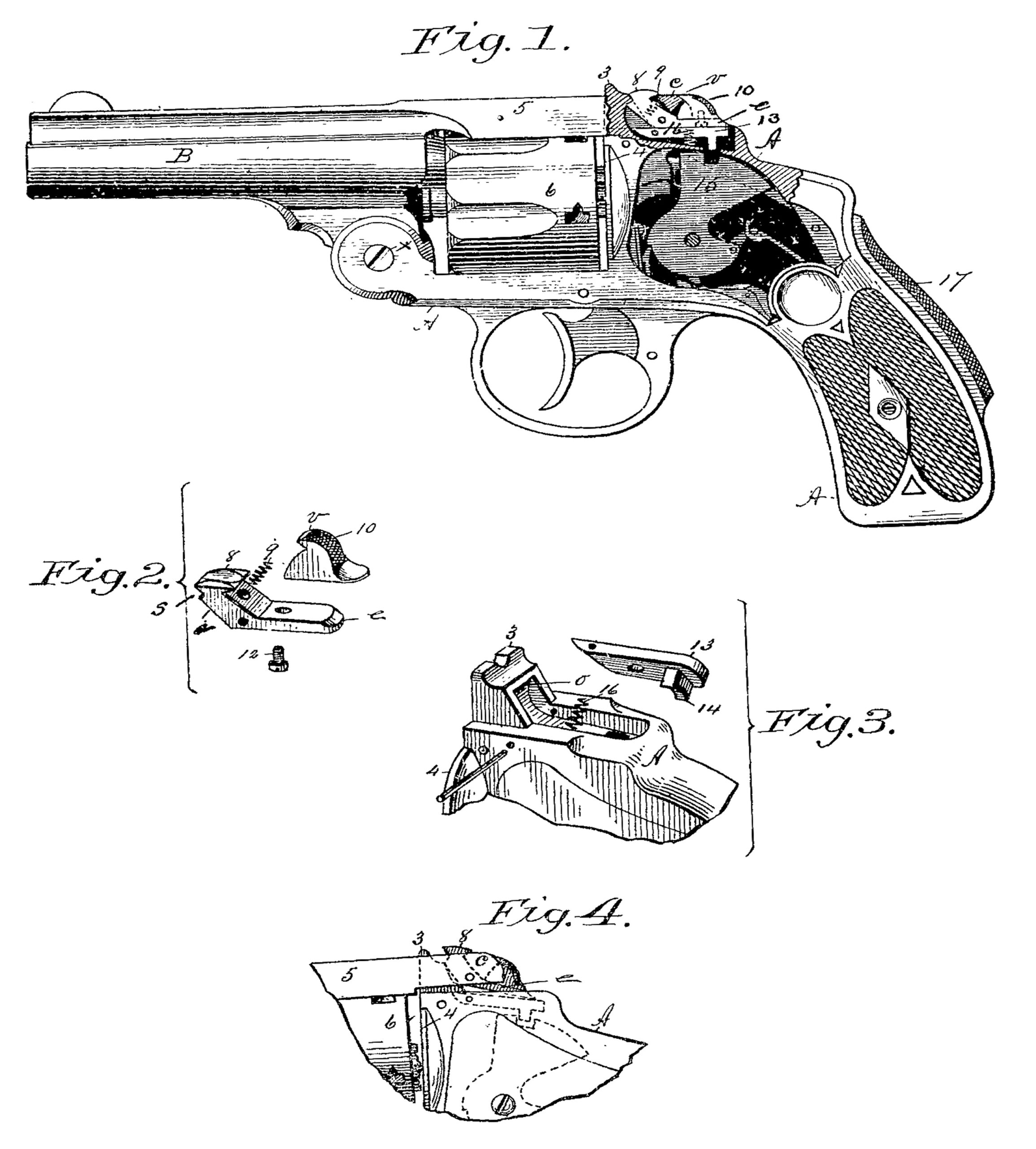
In the drawings forming part of this specification, Figure 1 is a side elevation of a revolving fire-arm embodying my invention, this figure showing the side plate removed and a part of the frame in section. Fig. 2 is a perspective view of parts of the barrel-catch, hereinafter described. Fig. 3 is a perspective view of that portion of the frame of the arm on which is located the catch-post, and of a hammer-stop and a spring which co-operates therewith. Fig. 4 is a side elevation of said part of the frame on which is the catch-post and of the tear end of the barrel-strap and of the cylinder.
In the drawings, A is the frame of the arm, having the usual catch-post 3,and recoil-plate 4 thereon.
B is the barrel, pivoted to the frame A at x, and having the barrel-strap 5 thereon, which extends over the cylinder 6, and is perforated to be engaged with the said catch-post. The cylinder 6 occupies the usual position at the rear of the barrel and when in firing position between the latter and said recoil-plate.
A catch 8 is pivoted to the rear end of the barrel-strap 5, its main portion being located within said catch-post perforation in said strap, and having its shank e extending rearwardly under the transverse part c of the rear end of the barrel-strap. A spring 9 (see Figs. 1 and 2) is interposed between said catch 8 and the barrel-strap, which acts to throw said catch against the rear side of the catch-post 3 and cause it to engage with the upper edge v of the recess o in avid post. A thumb-block 10 is secured to the upper side of said shank e of the catch by a screw 12, or other suitable means, the upper portion of said block 10 extending partially over said transverse part c of the rear end of the barrel-strap, as shown in Fig. 1. The said catch 8, which is a trifle narrower than the width of said socket o in the catch-post, has an inclined face a, extending from its lower side up to its catch-shoulders, which face rides on the upper border of said recess o, while the end of the barrel-strap is being carried over the catch-post, as shown in Fig. 4, to its finally locked position, (shown in Fig. 1,) and owing to the temporary contact of said face a with said upper border of the recess o the catch is tilted, as shown in Fig. 4, whereby the extremity of its shank e is thrown considerably downward toward the frame of the arm. The catch-shank is maintained in said inclined position from the time of the engagement of said face of the catch 8 with said border on the catch-post during the movement of said strap over said post to a locked position thereon, and when the end of said strap is brought closely against the part of the frame at the bass of said post the catch swings from said tilted position (actuated by spring 9) to that shown in Fig. 1,and its shoulder s becomes engaged with the catch-post, as shown in said last-named figure, thereby firmly locking the barrel-strap to the frame at the rear of the cylinder.
Heretofore the above-described barrel-catch mechanism substantially has been used by applicant in the manufacture of revolving fire-arms, and has uniformly served to perfectly and firmly secure the barrel-strap to the frame of the arm back of the cylinder when the end of said strap has been brought to its proper position against said frame, so that the catch S may become positively engaged with the catch-post, as above set forth; but owing to carelessness on the part of the operator, or possibly to the pressure of the heads of the cartridges more or less against the recoil-plate 4, when an attempt has been made to bring the barrel-strap to a locked position said catch has failed to engage with the catch-post, from the fact that the end of the barrel-strap has not been brought to its position against the frame surrounding said post, and thereby the parts have not become locked, as they should be before firing, and consequently if the arm be fired under said conditions the barrel, from the effect of the recoil of the exploded cartridge, is caused to swing out of position on the frame and occasion inconvenience and result in some accident, more or less serious, and the purpose of this invention is to provide safety appliances, as below described, co-operating with said catch devices and operating in conjunction therewith and with the hammer of the arm, which render it impossible that the arm shall be fired until the said catch devices come to a full and positive engagement with the catch-post of the arm.
The above-referred-to safety appliances consist of a lever 13, pivoted in a recess in the frame of the arm at the base of the catch-post 3, the said lever 13 having a part thereof or a boss 14 thereon for engagement with the hammer 15, the latter having at its upper end a notch or abutment, substantially as shown, with which the free end of said lever may engage when depressed toward said hammer, as indicated in dotted lines in Fig. 4. The normal position of said lever 13 is that shown in Fig. 1, its outer face being in a plane corresponding to that of the under side of the shank e of the catch 8 when the latter is in engagement with the catch-post 3. A spring 16 is interposed between said lever and the frame of the arm to hold the lever 13 in said normal position, and when occupying this position the boss on said lever interposes no obstacle to the freeswing of the hammer for firing. The said normal position of lever 13 is also maintained by the spring 16, while the barrel-strap is unlocked from the catch-post and swung entirely away from it; but when said strap is to be locked to the catch-post in “ closing the arm,” as it is termed, as is done after loading the cylinder with cartridges, and is brought to about the position shown in Fig. 4, the engagement of the face of the catch 8 with the rear side of the catch-post, as above described, causes said catch to be tilted and the extremity of its shank e to become engaged with the free end of said lever 13, thereby swinging the stud-bearing end of said lever downward toward the hammer and carrying its stud 14 into said slot in the hammer, and there holding it until the barrel-strap shall be brought closely against the frame of the arm at the base of the catch-post, (which is its locked position,) when catch 8 becomes engaged with said post, and said engagement causes the extremity of its shank to swing upward and allow the free end of lever 13 to follow its movement, thereby withdrawing the stud 14 from said notch in the hammer, so that the latter may be operated to fire the arm. The arm is opened by pressing on said thumb-block and tilting the catch 8 to disengage it from the catch-post and then swinging the barrel, as usual.
The lever 17, a well-known structural feature of pistols known as the “Smith & Wesson,” pivoted in the handle of the arm, has its inner end swung from behind the hammer in the act of grasping the arm to fire it.
What I claim as my invention is—
1. A revolving fire-arm having a lever pivoted in the frame of the arm to engage with the hammer thereof, combined with the catch-post on said frame, the barrel-strap, and a catch on said strap, which is tilted through engagement with said post, thereby causing one end thereof to engage with and depress one end of said lever, substantially as set forth.
2. In a revolving fire-arm, a catch-post on the frame thereof, the barrel-strap, a catch having a rearwardly-extending shank pivoted on said strap for engagement with said post, and the hammer, combined with a lever pivoted in said frame between said catch and hammer and depressible by the movement of a part of said catch against it to engage it with said hammer, and a spring to move said lever away from the hammer, substantially as set forth.
3. In a revolving fire-arm, the hammer hung in the frame thereof and having a notch in its upper end, a lever pivoted in said frame over said hammer, having a part thereof for engagement with said notch, and a spring holding said lever normally disengaged from the hammer, combined with the catch-post, the barrel-strap, a catch pivoted in said strap to engage with said post, having a shank extending over said lever, and a spring between said strap and catch to move the latter against said post, substantially as set forth.
DANIEL B. WESSON.
Witnesses:
H. A. CHAPIN,
G. M. CHAMBERLAIN.