
US 284786
UNITED STATES PATENT OFFICE.
DANIEL B. WESSON, OF SPRINGFIELD, MASSACHUSETTS.
REVOLVER.
SPECIFICATION forming part of Letters Patent No. 284,786, dated September 11, 1883.
Application filed July 17, 1882. Renewed June 25, 1883. (No model.)
To all whom it may concern:
Be it known that I, DANIEL B. WESSON, of Springfield, in the county of Hampden and State of Massachusetts, have invented a new and useful Improvement in Revolving Fire-Arms, of which the following is a specification and description.
The object of my invention is to provide a convenient and effective means for securing or locking the barrel portion of a revolving fire-arm to the frame and for unlocking the same, and of securing the chambered cylinder in its position at the rear of the barrel, and of releasing the same, when desired; and I accomplish this by the mechanism substantially as hereinafter described, and illustrated in the accompanying drawings, in which–
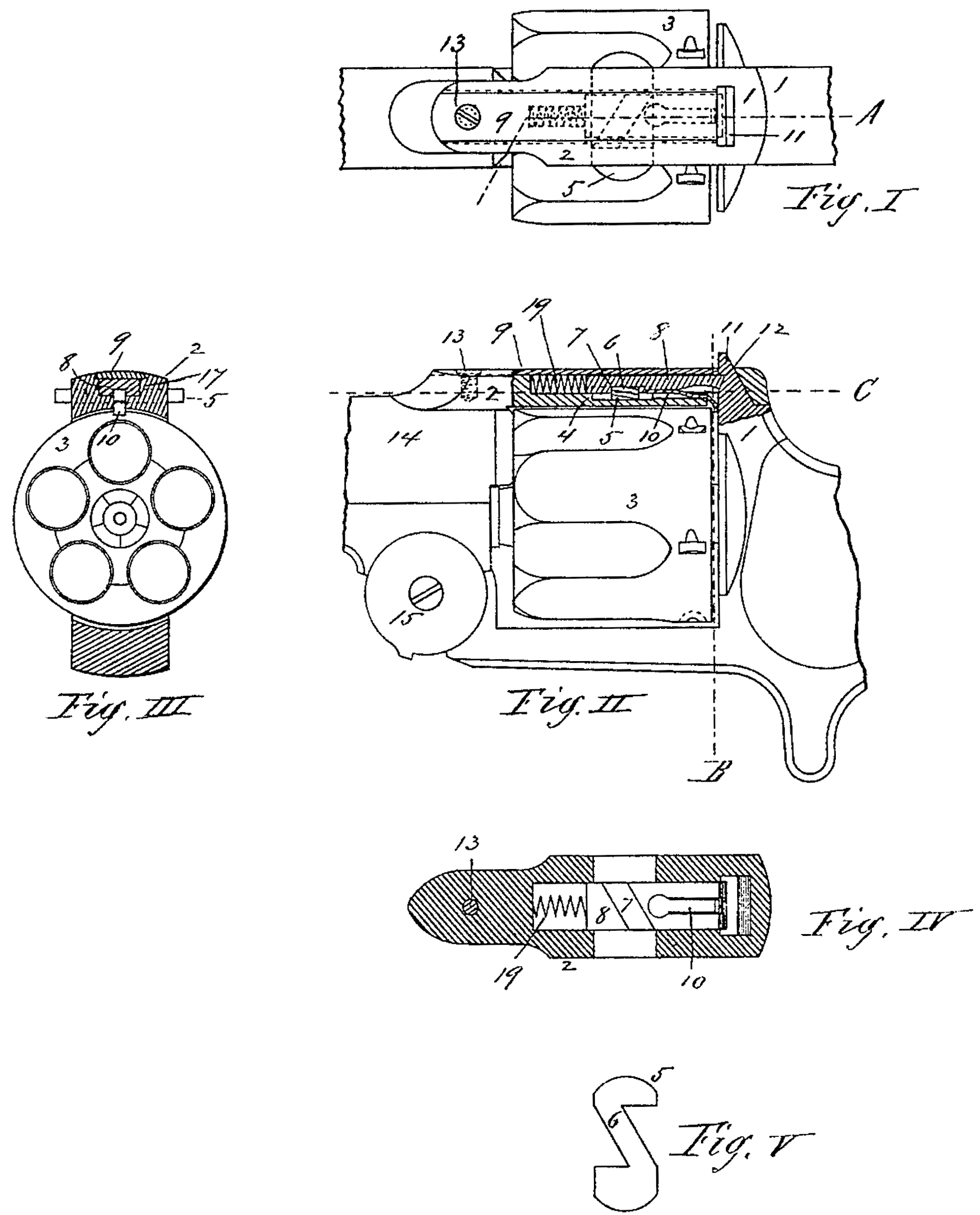
Figure I is a plan view of so much of a revolving fire-arm as is necessary to show my invention as applied thereto. Fig. II is a side view of the same with that part of the arm to which my invention is applied in longitudinal vertical section at line A of Fig. I. Fig. III is a transverse section of the same at line B of Fig. II. Fig. IV is a reverse plan view of the locking-bolt and horizontal section of the top strap at line C, and Fig. V is a plan view of the thumb-piece for operating the spring-latch.
In the drawings, 1 represents the frame of an ordinary revolving fire-arm. 14 represents the barrel pivoted to the frame at 15.
3 represents the cylinder, and 2 represents the top strap, which extends rearward from the barreland above the cylinder, and by which the barrel and cylinder are secured in place against the recoil-plate. In this case this top strap has a longitudinal cavity, as 17, made from its upper side, into which is inserted a sliding latch, as 8, having a cavity or recess, as 7, made obliquely across its lower side, as shown clearly in Fig. IV, and this latch is also recessed for a portion of its length, as shown at 18, to receive a spring or stop, as 10, which, being inserted in place in its recess, may be secured therein by upsetting the metal of the latch against and around it, or by any other suitable means.
5 represents a thumb-piece, whose edges at the ends are parallel and extend at right angles to the length of the strap, as 2, and whose ends are connected by a bar, as 6, having its edges parallel and inclined to the edges of the thumb piece at the ends, this bar extending across the latch, as 8, obliquely, and approximately fitting the oblique cavity, as 7, in the lower side of the latch, so as to slide to and fro therein. A spring, as 19, is placed in the recess 17 of the strap, so as to have a bearing against the end of the recess and the inner end of the latch, and keep the latter in its most rearward position, with its rear end in engagement with the catch, as 11, which extends upward through the strap from the frame, in rear of and above the cylinder, as shown in Fig. II. A slight longitudinal cavity, of dovetail form at its sides, is made in the top side of the strap, and a cover, as 9, with beveled edges to fit the dovetailed sides of the cavity, is fitted therein and secured, preferably, by a screw, as 13. The spring-stop, as 10, secured in the lower side of the latch, as 8, is inclined downward near its rear end, and its extreme rear end extends downward to a point just in rear of the rear end of the cylinder and near its periphery when all the parts are in place and the barrel is locked to the frame, or when the latch, as 8, is in its most rearward position, and the cylinder is then held in its position in rear of the barrel, and when the latch is moved forward the spring-stop, as 10, is moved forward also by the latch, and the incline of the stop rides over the rear end of the strap, as 2, at the point where the stop projects down through the strap, and the extreme rear end of the spring-stop is then withdrawn from its position in rear of the cylinder, and when in this position–with the latch moved forward–the cylinder may be removed from its position in rear of the barrel.
When it is desired to unlock the barrel from the frame, it is only necessary to press in the thumb-piece, as 5, and the oblique bar, as 6, on the thumb-piece, moving in the oblique recess, as 7, of the latch, pushes the latch for ward out of engagement with the catch 11 on the frame, and the barrel may then be tilted forward to expose the rear end of the cylinder, and, if desired, the cylinder may then be removed from its place in rear of the barrel; but as soon as the pressure against the thumb-piece is removed the spring, as 19, forces the latch rearward again, and the spring-stop, as 10, also moves back, with its extreme end in rear of the cylinder, to prevent the latter from being separated from the barrel, and yet allow it to revolve freely.
Having thus described my invention, what I claim as new is–
1. In a revolving fire-arm, the combination of a spring-latch adapted to move longitudinally in the top strap of the arm, and to engage at its rear end with a catch in the frame in rear of the strap, and provided with an oblique recess and a thumb-piece adapted to move transversely in said strap, and provided with an oblique bar to engage with said oblique recess in the latch, substantially as described.
2. In a revolving fire-arm, the combination of a spring-latch adapted to move longitudinally in the top strap of the arm, and to engage at its rear end with a catch in the frame in rear of the strap, and a spring-stop secured to said latch, and with its rear end extending downward in rear of the cylinder, and adapted to move against a shoulder on the strap, where by the cylinder is held to the barrel when the latch and stop are in their rearward position, and is free to be removed from the barrel when said latch and stop are moved forward, substantially as described.
DANIEL B. WESSON.
Witnesses:
T. A. CURTIS,
N. E. DWINNELL.