
US 251750
UNITED STATES PATENT OFFICE.
JOSEPH. H. WESSON, OF SPRINGFIELD, MASSACHUSETTS.
REVOLVING FIRE-ARM.
SPECIFICATION forming part of Letters Patent No. 251,750, dated January 3, 1882.
Application filed September 23, 1881. (No model.)
To all whom it may concern:
Be it known that I, JOSEPH. H. WESSON, of Springfield, in the county of Hampden and State of Massachusetts, have invented a new and useful Improvement in Revolving Fire-Arms, of which the following is a specification and description.
The object of my invention is to provide a cylinder-stop for a revolving fire-arm which is cheap, durable, and effective in its construction and operation, which is controlled in its engagements with the cylinder by the hammer tumbler through the medium of the rear sear, with which the stop, which extends through or past the trigger, is immediately connected, and I accomplish this by the construction substantially as hereinafter described, and illustrated in the accompanying drawings, in which–
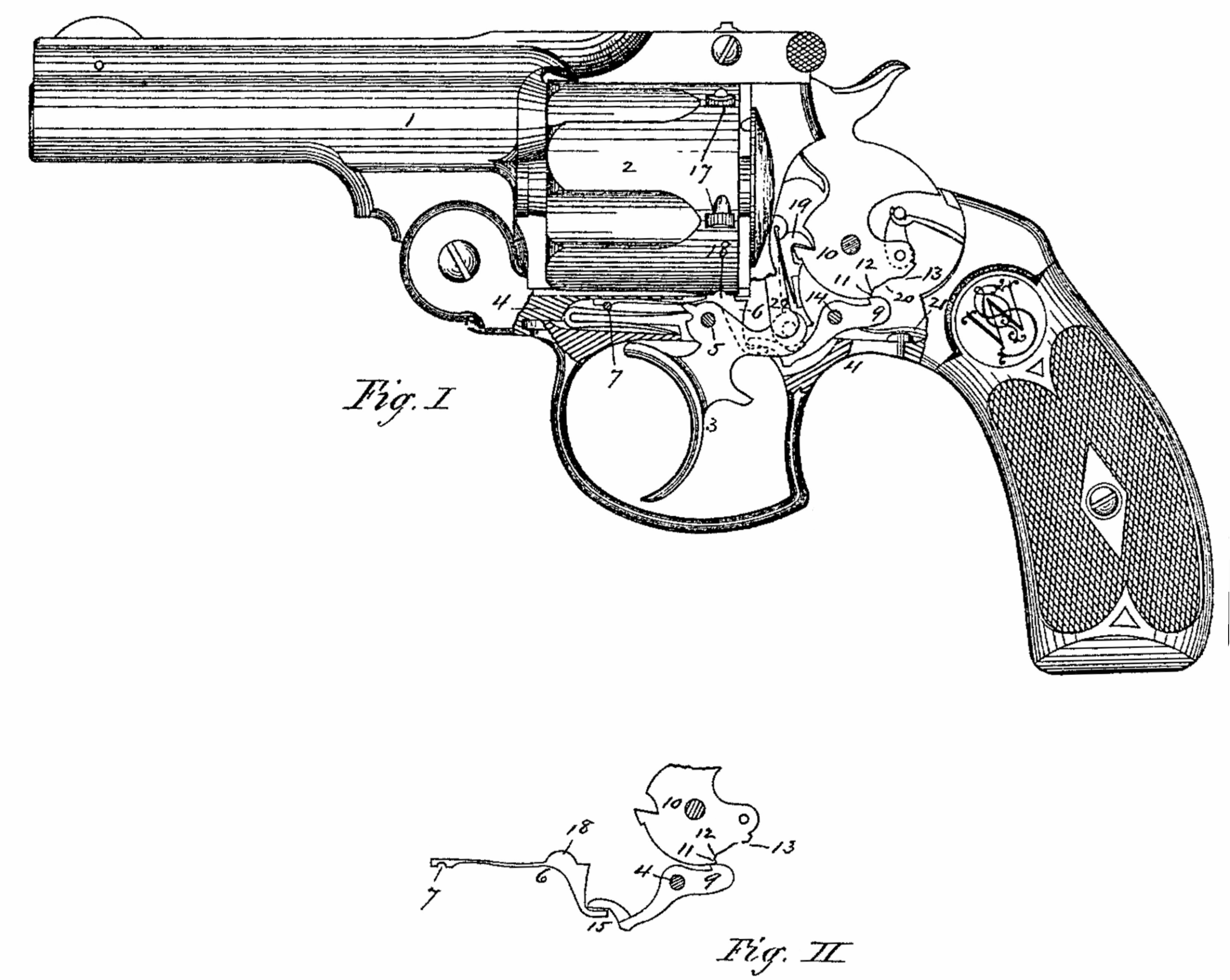
Figure I is a side view of a double-acting revolving fire-arm, with the lower portion of the frame broken away to show my invention as applied thereto; and Fig. II is a side view of the cylinder-stop, sear, and hammer-tumbler in the relative positions which they occupy in the arm, and their immediate connection with each other.
In the drawings I have shown my invention as applied to a double-acting revolver, in which 4 is the frame containing the revolving chambered cylinder, as 2, and 1 is the barrel, pivoted to the front lower portion of the frame. The trigger, as 3, is pivoted in the frame at 5, and is connected at its rear end with the front sear, as 19, and the trigger is either halved or mortised in its rear upper part in a direction lengthwise the arm, to permit the rear portion of the cylinder-stop to extend through or past that portion of the trigger, as shown in dotted lines in Fig. I.
The cylinder-stop, as 6, is made in the form of a spring, or elastic in its forward part, and is secured at its front end firmly in the frame by a pin at 7, and its rear portion above is provided with a protuberance, as 18, adapted to engage with the stop-notches, as 17, in the rear exterior portion of the cylinder, the lower rear part of the stop, as 15, extending through or past the recess made in the rear portion of the trigger.
The rear sear, as 9, is pivoted in the frame, as usual, at 14, and extends forward into a position and sufficiently far to engage with and depress the rear portion of the cylinder-stop, as shown in Fig. III and in dotted lines in Fig. I. The rear end of the sear 9 is provided with the ordinary catch to engage with the hammer-tumbler, and the tumbler is provided with the ordinary recess, as 20, which in this case is provided at one end with a short straight notch, as 11, and inside of that a short incline, as 12, and at the other end of said recess is a shoulder, as 13, which may be more or less inclined, as desired.
A spring, as 21, may be secured in any desired manner in the frame, to engage with and press the rear end of the sear, as 9, upward and into contact with the hammer-tumbler. When the hammer is down the rear end of the sear 9 bears up against the hammer-tumbler, as shown clearly in Fig. I, and the cylinder-stop is then in engagement with one of the cylinder-notches and the cylinder held stationary; and if the trigger is pressed back the front sear, 19, pivoted in the rear end of the trigger, moves the hammer backward a little in its cocking movement, and the rear end of the sear 9 is forced up into engagement with the short straight notch, as 11, by the action of the sear-spring 21, the hammer being then in its safety position, or at half-cock, the cylinder-stop being still in engagement with the notch in the cylinder. As the trigger is pressed still farther back the hammer is moved still farther backward in its cocking movement by the front sear, 19, and the catch on the rear end of the sear 9 rides up the short incline, as 12, which movement causes the front end of the sear 9 to depress the cylinder-stop and disengage it from the cylinder, when it is then free to be revolved by the upward movement of the hand, as 22, also connected with or pivoted to the trigger. As the backward cocking movement of the hammer continues, when the shoulder, as 13, comes in contact with the rear end of the sear 9, it depresses it, raising its front end and allowing the cylinder-stop to move up against the cylinder and enter the next notch to hold it stationary. It will thus be seen that in all these movements the action and movement of the cylinder-stop is caused by and communicated from the hammer-tumbler, through the medium of the sear 9, directly past and independent of the trigger, the latter having no connection whatever with the cylinder-stop.
It is evident that this invention is equally applicable to any ordinary revolving fire-arm as to what is known as a “double-acting revolver,” although I have illustrated it in the drawings as applied to the latter.
Having thus described my invention, what I claim as new is–
1. The combination, in a revolving fire-arm, of a cylinder-stop secured in the frame and adapted to engage in stop-recesses made in the cylinder and extending rearward past the trigger, a sear pivoted in the frame and whose forward end engages with said cylinder-stop, a sear-spring to hold the sear into contact with the hammer-tumbler, and a hammer-tumbler adapted to engage with the rear end of said sear, and thereby actuate the cylinder-stop in disengaging it from the cylinder independently from the trigger, substantially as described.
2. The combination, in a revolving fire-arm, of a hammer-tumbler provided with a safety-notch and an incline or shoulder just in rear of said safety-notch, a sear pivoted in the frame and whose catch is held in contact with the hammer-tumbler by a spring, and a cylinder-stop pivoted in the frame and adapted to engage in stop-recesses in the cylinder, and whose rear portion extends rearward past the trigger and into engagement with the sear, whereby the said cylinder may be locked when the catch of the sear is in the safety-notch of the tumbler, and is released by the further backward movement of the hammer, substantially as described.
JOSEPH WESSON.
Witnesses:
T. A. CURTIS,
E. M. BISSELL.