
US 217562
UNITED STATES PATENT OFFICE.
DANIEL B. WESSON, OF SPRINGFIELD, MASSACHUSETTS.
IMPROVEMENT IN MAGAZINE FIRE-ARMS.
Specification forming part of Letters Patent No. 217,562, dated July 15, 1879; application filed October 26, 1878.
To all whom it may concern:
Be it known that I, DANIEL B. WESSON, of Springfield, in the State of Massachusetts, have invented a new and useful Improvement in Revolving Fire-Arms; and that the following is a full, clear, and exact description thereof, reference being had to the accompanying drawings, making a part of this specification, and to the letters of reference marked thereon.
The object of my invention is to automatically move each cartridge in a revolving firearm forward, as it is brought into line with the bore of the barrel, sufficiently far that it shall occupy a portion of the bore of the barrel and a portion of the bore of the cylinder at the time of the explosion, and to withdraw the shell from the barrel after the explosion, said movement of the shell being accomplished by the ordinary movements of the hammer.
To this end my invention consists of a movable breech connected with the hammer, both being combined with the revolving cylinder in such manner that as each cartridge is brought into line with the bore of the barrel the breech-piece, provided with a hook at its forward end and actuated by the movement of the hammer forward, will force the cartridge forward partially into the barrel, the shell of the cartridge packing the joint between the cylinder and barrel at the time of the explosion, after which, by the backward movement of the hammer, the shell is drawn back into the cylinder, and is afterward removed, all which will be more fully hereinafter described.
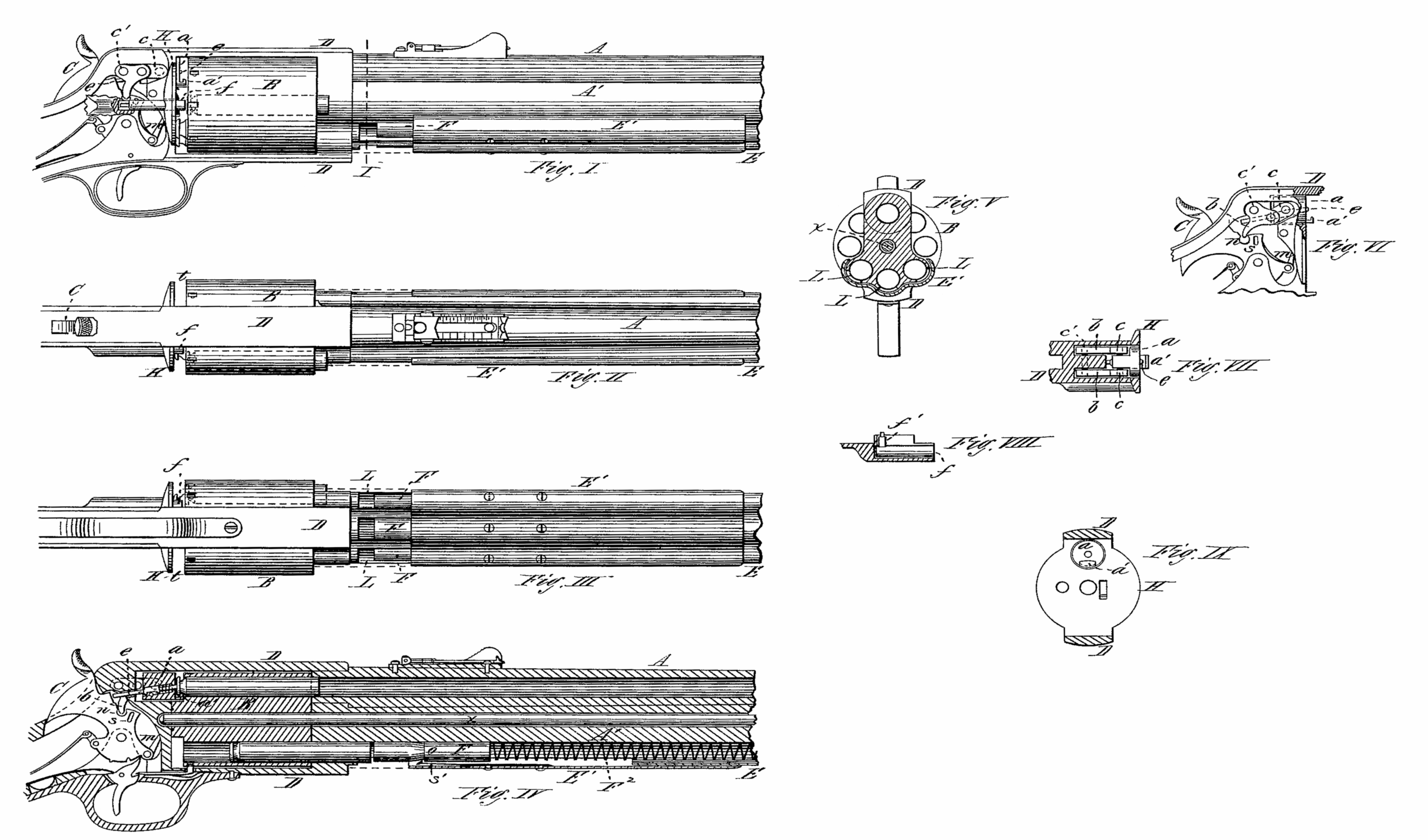
Figure I is a side view of a revolving fire-arm having my invention applied, and showing the slide of the magazine moved forward. Fig. II is a plan view of the same. Fig. III is a reverse plan view of the same, showing the slide of the magazine moved forward. Fig. IV is a vertical longitudinal section of the same at the axis of the barrel. Fig. V is a transverse vertical section at line I of Fig. I. Fig. VI is a side view of the hammer and mechanism which operates the movable breech. Fig. VII is a horizontal section of the frame at the axis of the movable breech, showing the latter in place and the pieces pivoted thereto which operate it. Fig. VIII is a horizontal section of the socket in which the ejector operates on the plane of its axis, showing the ejector and pin which connects it with the hammer; and Fig. IX is a front view of the recoil-shield.
In the drawings, A represents the barrel, D the frame, and B the cylinder, of a revolving fire-arm, with a piece, A’, extending along beneath the barrel, and the cylinder revolves upon a rod, x, which may be inserted or withdrawn at the forward end of this piece A’. The cylinder may be revolved, in the ordinary manner, by a series of teeth on the rear-end of the cylinder, and a hand, m, pivoted to the tumbler of the hammer; but the cylinder is made considerably shorter than the space in the frame in which it revolves, as shown clearly at t, for reasons which will be hereinafter set forth.
A space or recess is made in the upper part of the frame, and in a line with the bore of the barrel, into which is fitted to move freely a block, a, which I denominate the “movable breech,” the forward end of which, on its lower side, is provided with a hook, a’, as seen clearly in Figs. I and VI, and to this movable breech-piece a are pivoted the side pieces, c, which are jointed or toggled to the pieces b. These pieces b are pivoted at c’ to the frame D, so as to allow them a swinging movement in a vertical direction, and a projection is made on their lower part, which engages into a recess, n, made in the hammer, as shown clearly in Figs. IV and VI, so that as the hammer is drawn back the pieces b are drawn down at their forward part, and the movable breech-piece a is drawn back a little; but if the hammer is moved forward the piece a is moved forward. The latter is made of such length that when the hammer is in its most forward position the forward end of the piece a protrudes through the face of the recoil-shield a little, as shown clearly in Fig. I; but if the hammer is drawn back the plane of the forward end of the piece a is a little in the rear of the plane of the face of the recoil-shield. The fire-pin e is arranged in the piece a with its ordinary spring and stop, its rear end extending back between the pieces b, so that it can be struck by the hammer when the latter moves forward, as shown in Fig. IV.
A slot or recess, s, is made in the side of the hammer, into which engages a pin, f’, made on the inside of a bolt, f, sliding longitudinally in a socket or recess made in the frame, so that when the hammer moves forward the bolt is forced forward, and when the hammer is moved back the bolt f is thereby drawn back also; and this bolt f is of such length that when the hammer is in its most rearward position, or at full-cock, the forward end of the bolt is on the same plane as the face of the recoil-shield, and when the hammer is in its most forward position, or against the fire-pin c, the forward end of the bolt extends forward nearly to the rear face of the cylinder, as shown in Figs. I, II, and III.
Any other desired form of ejector may be used, however, as this arrangement of the bolt f is not an essential feature of my invention.
A magazine, E, may be arranged beneath the barrel, provided with the ordinary spring F2 and a plunger, F, and a cover or slide, E’, is clasped around the magazine E, or otherwise arranged to slide lengthwise thereon, but so as to remain firmly in any position in which it may be left.
I make a shoulder, o, on the plunger, and attach a spring-catch, s’, on the inside of the slide E’, so that if the slide be moved forward the spring-catch s’ engages against the shoulder o and moves the plunger F forward also, compressing the spring F2. In connection with this arm I use a cartridge whose shell is longer than the cylinder and nearly as long as the space in the frame in which the cylinder revolves, and the ball of which is inserted its entire length into the shell, and the flange of the shell being of the same diameter as the body of the shell, so that the cartridge may pass entirely through the chamber of the cylinder, and out at its forward end, the flange being made by an annular groove at the head, as shown clearly in the drawings.
Instead of using a single tube for the magazine, I use any desired number. In the drawings I have shown a series of three arranged side by side beneath the barrel.
The operation of my invention is as follows: The cartridges are inserted into the front end of the chambers of the cylinder at the side of the barrel, and when one is inserted the cylinder is rotated a little to bring the next chamber into position to receive a cartridge, and so on until all the cartridges have been inserted, and as the cylinder is rotated each time the flange of each cartridge is brought into a position immediately behind the hook a’, and the cartridge is then in a position to be discharged, the hammer being at a position of half-cock while the cylinder is being charged. The hammer being drawn back to a position of full-cock, the toggle-pieces b and c are drawn down, and the movable breech a is also drawn back to a position slightly in rear of the face of the recoil-shield H, and the bolt f is also drawn back by the hammer.
When the hammer is let forward again by the trigger, the toggle-pieces b and c are thrown up quickly, and the piece a is forced forward, which forces the cartridge forward so that its front end enters the rear end of the barrel, and the joint between the rear end of the barrel and the forward end of the cylinder is thoroughly and effectually packed, so that no gas from the explosion can escape through that joint, and the whole force of the explosion is utilized to expel the ball from the barrel. When the hammer is again moved back to a full-cock, the piece or movable breech a is also drawn back, drawing back also the empty shell to its original position in the chamber, and the cylinder is revolved by the hand m, and the next cartridge is thus brought into position with its flange behind the hook a’, and the forward movement of the hammer drives that cartridge forward, with its front end projecting into the barrel, packing the joint between the rear end of the barrel and front end of the cylinder, as before. This, in turn, is drawn back by the next backward movement of the hammer, and the cylinder is rotated as before, and the first empty shell is then in a position immediately in front of the bolt f, and when the hammer next moves forward to explode the cartridge then in position the bolt f is carried forward with a quick movement, striking against the first emptied shell, forcing it out the forward end of the cylinder, and clear from the gun. This firing of the cartridges may be continued and the empty shells ejected as long as any cartridges remain in the cylinder, and very rapidly, by the simple movement of the hammer in cocking and firing.
If it should be desired to continue this rapid firing longer than one round of cartridges contained in the cylinder alone, the slide E’ beneath the barrel is moved forward, which also moves forward the plungers F, so that cartridges may be placed in the tubes until the magazine is filled. The tubes L of the magazine are in direct line with the corresponding chambers of the cylinder, and when thus loaded, when the chambers of the cylinder are loaded also, the cartridges in the magazine cannot enter the chambers of the cylinder; but the first chamber that is emptied by the ejection of the shell in firing is quickly reloaded by a cartridge passing back into it as soon as the empty chamber gets into line with the first tube of the magazine. This magazine, being made with a series of tubes, may be made to contain any desired number of’ cartridges,so that when the chambers of the cylinder are all loaded, and the magazine is loaded also, the rapid discharge of cartridges may be kept up, by the simple movements of the hammer in cocking and firing, as long as any cartridges remain in the magazine.
This invention may be used upon small revolving fire-arms as well as upon large ones with equal facility.
It will be seen that this movement forward of every cartridge partially into the barrel as it comes into line and is discharged is a very important feature, as the joint between the forward end of the cylinder and the rear end of the barrel is most effectually packed to prevent the escape of gas, which escape has been one of the most serious objections to the use of large revolving fire-arms for long and accurate shooting, and this objection my invention entirely obviates. In as much as no part of the gas of the explosion comes in contact with the interior of the cylinder-chambers, or with the exterior of the cylinder, at the joint between the latter and the barrel, it is evident that the ordinary “fouling” of the cylinder is entirely obviated, and all the difficulties arising from that cause, in the proper working of the parts, are also obviated by my invention.
It is obvious that the piece a may be operated, or caused to move to and fro, by a cam or other mechanism, as well as by that hereinbefore mentioned.
Having described my invention, what I claim, as new is—
The combination of the revolving cylinder, the movable breech-piece with its hook, and the hammer, operating together in such a manner as that the bores of the cylinder and a portion of the bore of the barrel together form the chamber in which the cartridge is exploded, substantially as and for the purpose described.
DANIEL B. WESSON.
Witnesses:
T. A. CURTIS,
A. D. COPELAND.