
US 222167
UNITED STATES PATENT OFFICE.
DANIEL B. WESSON, OF SPRINGFIELD, MASSACHUSETTS.
IMPROVEMENT IN REVOLVING FIRE-ARMS.
Specification forming part of Letters Patent No. 222,167, dated December 2, 1879; application filed May 13, 1879.
To all whom it may concern:
Be it known that I, DANIEL B. WESSON, of Springfield, in the State of Massachusetts, have invented a new and useful Improvement in Revolving Fire-Arms; and I do hereby declare that the following is a full, clear, ard exact description thereof, reference being had to the accompanying drawings, making a part of this specification, and to the letters of reference marked thereon.
My invention relates to a revolving fire-arm in which a chambered cylinder is used in connection with a single barrel, and in which each chamber of the cylinder and a portion of the bore of the barrel form the chamber in which the cartridge is exploded; and the object of my invention is to force the cartridge forward a little, so that the front part of the shell will be in the rear part of the bore of the barrel, and when the explosion occurs the shell will pack the joint between the cylinder and barrel, and prevent the escape of gas. Its object is also to operate the hammer, as in the operation of firing, either with or without the rotation of the cylinder.
To this end my invention consists, first, of a reciprocating breech-piece, combined with a pivoted auxiliary tumbler having a limited rotary movement, and a thumb-piece having a movement independent of the hammer, and arranged to give a partial rotary movement to said auxiliary tumbler and a reciprocating movement to the breech-piece; and it also consists of a shouldered link, combined with the reciprocating breech-piece and a brace, whereby the latter, being actuated by the tumbler, causes the link to draw back the firing-pin as the hammer is moved away from the rear end of the pin, all of which will be more fully hereinafter described.
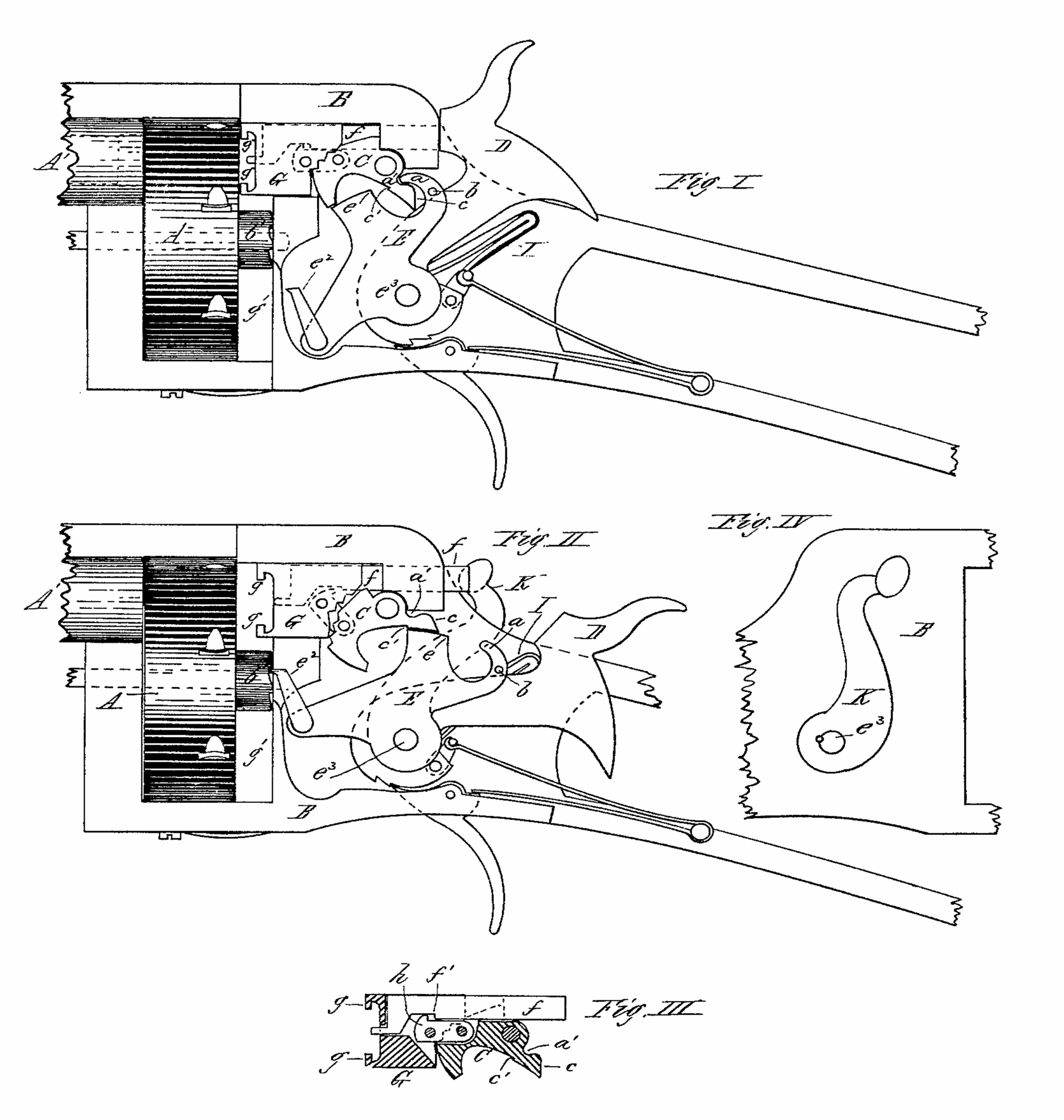
Figure I is a side view of a portion of a revolving fire-arm made according to my invention, with the lock-plate or side of the frame removed, and showing the parts of the lock mechanism in place, with the hammer thrown forward against the firing-pin. Fig. II is a side view of the same, showing the parts in position when the hammer and thumb-piece are thrown back. Fig. III is a longitudinal vertical section through the middle of the movable breech-piece and brace, showing the link which connects them, and which moves back the firing-pin; and Fig. 1V is a reverse side view of the frame, showing the lever or thumbpiece secured to the hammer-pivot.
In the drawings, A represents the chambered cylinder, A’ the single barrel, B the frame, and D the hammer, of a revolving firearm, in which a space, g’, is left between the cylinder and that part of the frame directly behind it; and to the hammer-pivot e3, which is arranged with a limited reciprocating rotary movement, is rigidly secured a lever or thumbpiece, K, and also an auxiliary tumbler, E, the latter provided with a projection, c, on its forward part, and behind this another curved projection, a. This tumbler is also provided with a shoulder or projection, b, which, when the tumbler is moved back, impinges against the hammer and moves that back also. The hand or pawl e2, which engages with the ratchet on the rear end of the cylinder to turn it, is also pivoted to this tumbler at the lower end.
A brace, C, is pivoted in the frame above the tumbler E, and this brace is provided with a small shoulder, c’, on its lower side, and an incline, c, on its rear side, the purpose of which will be more fully hereinafter explained; and the forward end of this brace is shouldered or fitted against the rear end of the movable breech-piece, G, and is connected therewith by a link, h, pivoted at one end in the front part of the brace, and at the other end in the rear part of the piece G, as shown clearly in Fig. III, aid in dotted lines in Figs. I and II. The movable breech-piece G is provided with hooks g, one or more, at the front end, and slides to and fro in the frame, and this piece G and the brace C are recessed longitudinally to receive the firing-pin f, which is arranged to slide lengthwise therein. The link h, pivoted to the piece G and to the brace C, is provided with a shoulder at the top, near the forward end, which, when the brace is tilted downward, engages with a shoulder, f’, on the firing-pin, and moves the latter backward into a position to be struck by the hammer.
A spring, I, is fixed in the frame, one end of which spring is so connected with the hammer-pivot e3 as to cause the thumb-piece K and auxiliary tumbler E (both rigidly connected to the hammer-pivot) to remain in a position tilted forward, and the piece G also to remain in its most forward position, with the brace C firmly against its rear end, as shown clearly in Figs. I and III.
The operation of my invention is as follows: The cartridges are inserted into the chambers with their heads protruding from the rear end of the cylinder nearly as far as the width of the space g’ between the cylinder and frame. When the parts are in the position shown in Fig. I, if the thumb-piece or lever K is pulled back into the position shown in Fig. I, the tumbler E is moved back also by the rotary movement of the hammer-pivot e3, the pin or projection b forcing the hammer back also until the sear enters the cock-notch. As the auxiliary tumbler E starts to move back, the upper rear corner of the projection c strikes against the shoulder c’ on the brace C and throws the rear end of the brace upward, and moves the forward end of the brace and the rear end of the link h downward, and this movement draws the breech-piece G rearward, and also, by the contact of the shoulder on the link with that on the firing-pin f, draws the latter backward also, until, when the hammer is cocked, the parts are in the position shown in Fig. II. During the latter part of this backward movement of the tumbler E the cylinder A is revolved partially by the hand or pawl e2; but this rotary movement does not begin until after the piece G has reached its rearward position, (shown in Fig. II,) and as the cylinder revolves the head of a cartridge is carried into a position behind the hooks g, or with the hooks within the annular groove in the cartridge. When the thumb is released from the thumb-piece, the spring I partially rotates the hammer-pivot e3, carrying forward the thumbpiece and the auxiliary tumbler E, the end of the curved projection a on the latter striking against the incline c on the rear end of the brace, and thereby moving its forward end upward, and forcing the piece G forward and the front end of the cartridge into the rear end of the bore of the barrel, the firing-pin f remaining in its backward position, into which it was moved by the downward movement of the link h. The trigger being pulled, the hammer thus released strikes the firing-pin and explodes the cartridge, and upon pulling back the thumb-piece in the next operation of cocking the hammer the piece G is drawn back and the cartridge is withdrawn from the rear end of the barrel, and the next partial rotation of the cylinder carries the empty shell around to one side into a position to be removed from the chamber.
If the cartridge should fail to explode at the first attempt, as the hammer swings loosely upon its pivot e3, other attempts may be made to explode it without moving it or the cylinder by taking hold of the hammer and cocking it in the usual manner, instead of cocking it by the thumb-piece K, in which case the cylinder will remain stationary until the thumbpiece is again drawn back.
It will be seen that when the cartridge explodes, the forward end of the shell is within the rear part of the bore of the barrel, so that the shell forms a perfect packing to prevent the escape of gas at the joint between the cylinder and the barrel.
In the use of this arm the cylinder may be rotated or not by simply using the thumb- piece K to cock the hammer, or by using only the hammer itself, as may be desired, the hammer being actuated to strike the firing-pin by the ordinary mainspring and stirrup.
The spring I, to keep the thumb-piece K and auxiliary tumbler E always in their most forward position, may be omitted, in which case it will be only necessary to move the thumbpiece forward after moving it back each time; but I prefer to use it, as it quickly moves the cartridge forward into place, which should it fail to do from any cause additional force may be applied by pressing the thumb-piece forward, it is evident that the hammer may be arranged to swing upon a pivot independent from that upon which the thumb-piece and tumbler are attached without departing from the principle of operation above described.
Having thus described my invention, what I claim as new is—
1. The combination of the reciprocating breech-piece G, the brace C, and link h, connecting said breech-piece and brace, the auxiliary tumbler E, and the thumb-piece or lever K, substantially as and for the purpose described.
2. The combination of the reciprocating breech-piece G, the brace C, and link h, connecting said breech-piece and brace, the auxiliary tumbler E, and hammer D, with its pivot, substantially as described.
DANIEL B. WESSON.
Witnesses:
T. A. CURTIS,
GEORGE B. RATHBUN.