
US 323837
UNITED STATES PATENT OFFICE.
DANIEL B. WESSON AND JOSEPH H. WESSON, OF SPRINGFIELD, MASS.
REVOLVING FIRE-ARM.
SPECIFICATION forming part of Letters Patent No. 323,837, dated August 4, 1885. Application filed February 5, 1885. (No model.)
To all whom it may concern:
Be it known that we, DANIEL B. WESSON and JOSEPH H. WESSON, citizens of the United States, residing at Springfield, in the county of Hampden and State of Massachusetts, have invented new and useful Improvements in Revolving Fire-Arms, of which the following is a specification.
This invention relates to improvements in revolving fire-arms, and pertains to the lock mechanism thereof, the object being to provide in a fire-arm improved devices for preventing the hammer from being operated inadvertently, for causing the point of the firing pin to retire from the head of the cartridge after receiving the blow of the hammer, and for operating the sear.
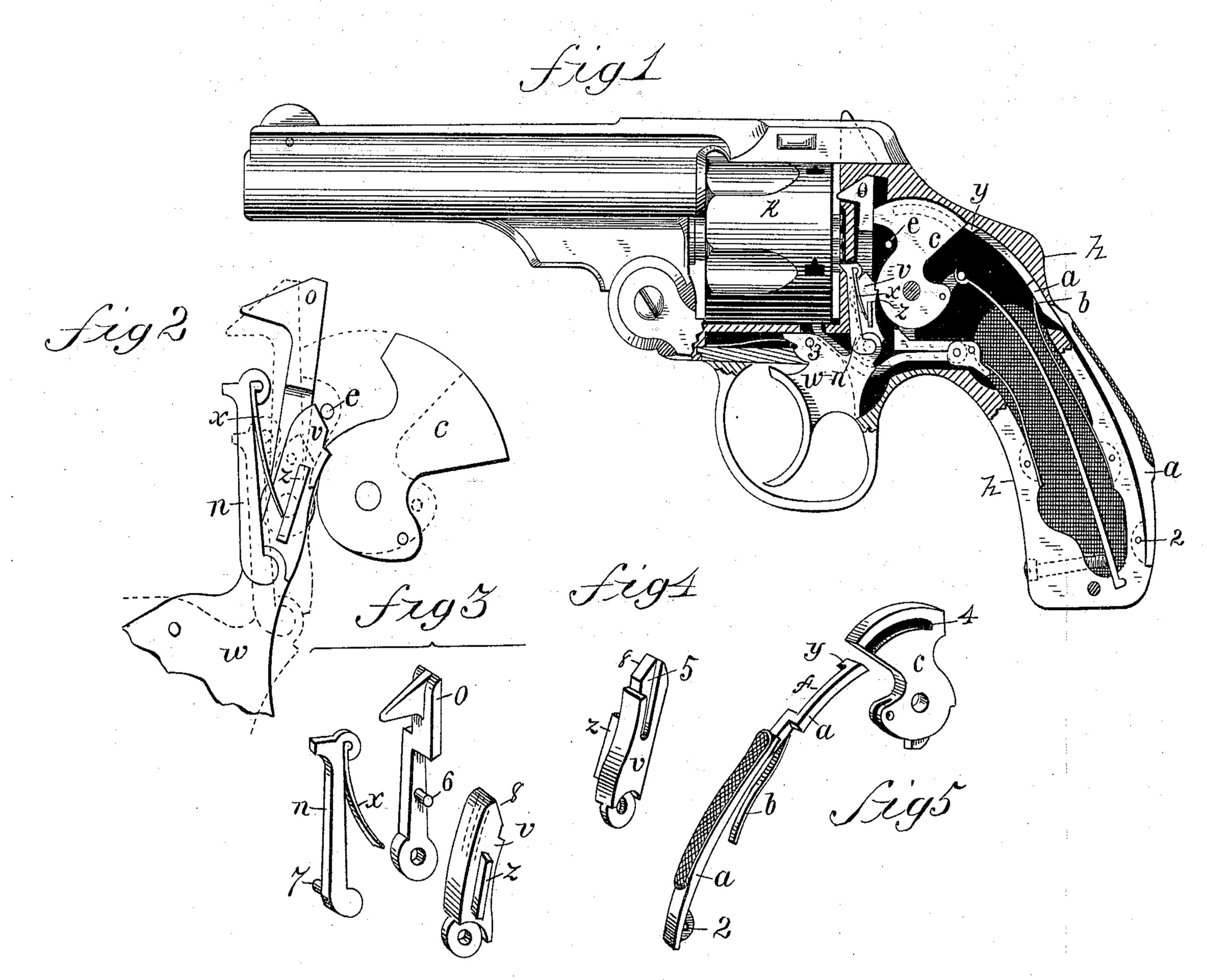
In the drawings forming part of this specification, Figure 1 is a side elevation of a revolving fire-arm, partly in section, embodying our improvements. Fig. 2 is a side elevation on an enlarged scale of the principal parts of the lock mechanism detached from the arm. Figs. 3, 4, and 5 illustrate detail parts, which will be hereinafter referred to and described. In the drawings, h indicates the handle portion of the frame of the arm, the hammer c being hung in the frame in its usual position and manner, and connected with a mainspring, as usual. The hammer, however, has formed in one side thereof a curved groove, 4, concentric with its pivot, said groove being shown fully in Fig. 5 and in dotted lines in Fig. 1. The hammer is provided with the usual sear-catch, as shown.
On the rear or bearing side of the handle h is pivoted at 2 a lever, a, which extends outside of the handle from just below said pivot-point to about the point opposite the letter b, where there is an offset in the lever, carrying its upper end inside the handle through an opening in the latter, said upper end of the lever extending upward to the rear edge of the hammer c, and being held up against the inner side of the handle by the spring b, so that the end of the lever is opposite that portion of the rear edge of the hammer which is above the end of the curved groove 4.
The lever a has a lateral offset, f, in it to carry its upper end to one side of the line of movement of the hammer when the latter swings backward, and at its end a lateral projection, y, which when the lever is depressed is brought from opposite the upper end of the hammer down opposite the open end of the groove 4; and when in this latter position the end of the lever presents no obstacle to the cocking of the hammer, the projection y being in said groove when the hammer swings.
The lever 4 is depressed to carry its upper end downward opposite the end of the groove 4, as above stated, by the natural force of the grip of the hand on the handle when the arm is taken in the hand to be fired and the trigger w is pulled upon to cock the hammer; but unless said lever is so depressed the hammer cannot be cocked, as its upper end is directly behind the solid part of the hammer above the slot 4.
Heretofore in this class of lock mechanism a spring has been employed to swing the firing-pin from the head of the cartridge in the cylinder and retain it in proper position to be struck by the hammer; but such a spring proves in practice to bea source of inconvenience, since it acts more or less to retard the blow of the hammer when the spring is strong enough to act, as above stated, on the firingpin; and when said spring is too weak it permits the point of the firing-pin to remain engaged with the head of the cartridge and hinder the rotation of the cylinder. In this construction said spring is discarded and the firing-pin is governed by the improved devices hereinafter described.
The firing-pin o is pivoted on the inside of the frame in front of the hammer, and has in its side next to the sear v a pin, 6. (See Fig. 3.)
The sear and the pawl n are pivoted on an arm of the trigger w in the usual manner, the sear having the groove 5 in its side next to the firing-pin, into which the pin 6 on the latter reaches, whereby the sear and firing-pin are engaged with each other, but the former is free to move vertically by the side of the latter, but a certain amount of vibratory motion given to the sear, as hereinafter described, is imparted to the firing-pin.
The sear v has a projecting lip, z, on its outer side, which serves as a bearing for the free end of the spring x, which is secured to the pawl n near its free end. The upper end of the sear v is beveled off at 8, as shown.
A trip-pin, e, is placed in the side of the frame just forward of the hammer, and is of a length about equal to the thickness of the latter. Said pin is directly in the line of movement of the end of the sear when the latter has carried the hammer to a full-cock position, as shown in Fig. 2, and at that stage of the movement of the parts the said beveled end of the sear is forced against the side of pin e, and the sear is tripped or disengaged from the hammer c, letting it strike the firing pin o.
When the sear moves upward to cock the hammer, as above described, the firing-pin is liberated so that it may go toward the hammer without resistance, and when the hammer strikes the firing-pin the latter is free to swing toward the cylinder to the position shown in Fig. 1 and in dotted lines in Fig. 2.
When the sear is down, the engagement of pin 6 in the groove in the sear causes the firing-pin to be retired from the cylinder.
The spring x on the pawl n is sufficiently active to hold the latter in engagement with the ratchet-teeth on the rear end of the cylinder k when the sear has swung away from the pawl to its greatest limit, as in Fig. 2, and after the hammer has struck the firing-pin the spring x, acting against lip z, on the sear, throws the latter against the hammer, as in Fig. 1, insuring its engagement with the latter, (in this case acting as a sear-spring,) and the sear in so swinging carries the firing-pin with it, bringing the latter toward the hammer and drawing the firing-pin back from the end of the cylinder far enough to clear it from the head of a cartridge-shell which has been struck by it, so that the cylinder may rotate freely, when the trigger w is again pulled to fire the arm.
What we claim as our invention is—
1. In a fire arm, a lever pivoted at one end on the rear outside of the handle of the arm, and constituting substantially the outer bearing-surface of the handle, having its free end passing through an opening in the latter and terminating behind the hammer, a hammer having a groove in its side to receive the end of said lever, and a spring to throw the free end of the latter to one side of the open end of said groove, combined and operating substantially as set forth.
2. In fire-arm-lock mechanism, a firing-pin, substantially as described, pivoted to the frame in front of the hammer, a sear pivoted on the trigger by the side of said firing-pin, and engaging with the latter, substantially as described, and a spring located between the pawl and the sear to swing the latter toward the hammer, combined and operating substantially as set forth.
3. In fire-arm-lock mechanism, a tripping-pin located on the frame of the arm forward of the hainmer, and a sear having a movement toward said pin, and carried against the latter when the hammer swings to full cock, combined with the hammer and the trigger, substantially as set forth.
4. In combination, the trigger pivoted in the frame of the arm, the sear pivoted on the trigger, and having a groove in its side adjoining the firing-pin, the spring x, attached to the rear side of the pawl and its free end pressing against the lip z on the sear, the pivoted firing-pin having a pin on its side engaging in said groove in the sear, and the hammer, substantially as set forth.
DANIEL B. WESSON,
JOSEPH H. WESSON.
Witnesses:
H. A. CHAPIN,
J. D. GARFIELD.