
US 354545
UNITED STATES PATENT OFFICE.
DANIEL B. WESSON, OF SPRINGFIELD, MASSACHUSETTS
RELOADING CARTRIDGE-PACK.
SPECIFICATION forming part of Letters Patent No. 354,454, dated December 14, 1886.
Application filed August 4, 1886. Serial No. 209,994. (No model.)
To all whom it may concern:
Be it known, that I, DANIEL B. WESSON, a citizen of the United States, residing at Springfield, in the county of Hampden and State of Massachusetts, have invented new and useful Improvements in Reloading Cartridge-Packs for Fire-Arms, of which the following is a specification.
This invention relates to improved means for arranging a suitable number of cartridges together for reloading the cylinder of revolving firearms, in what I term a ‘‘reloading- pack,’’ the object being to secure six cartridges (more or less) in a group, and in positions identical to those which they assume when placed in one of said cylinders, which group is united by a casing which permits of their safe and convenient transportation, but which becomes disconnected from the cartridges and falls away therefrom by the act of placing the latter in the cylinder of the arm.
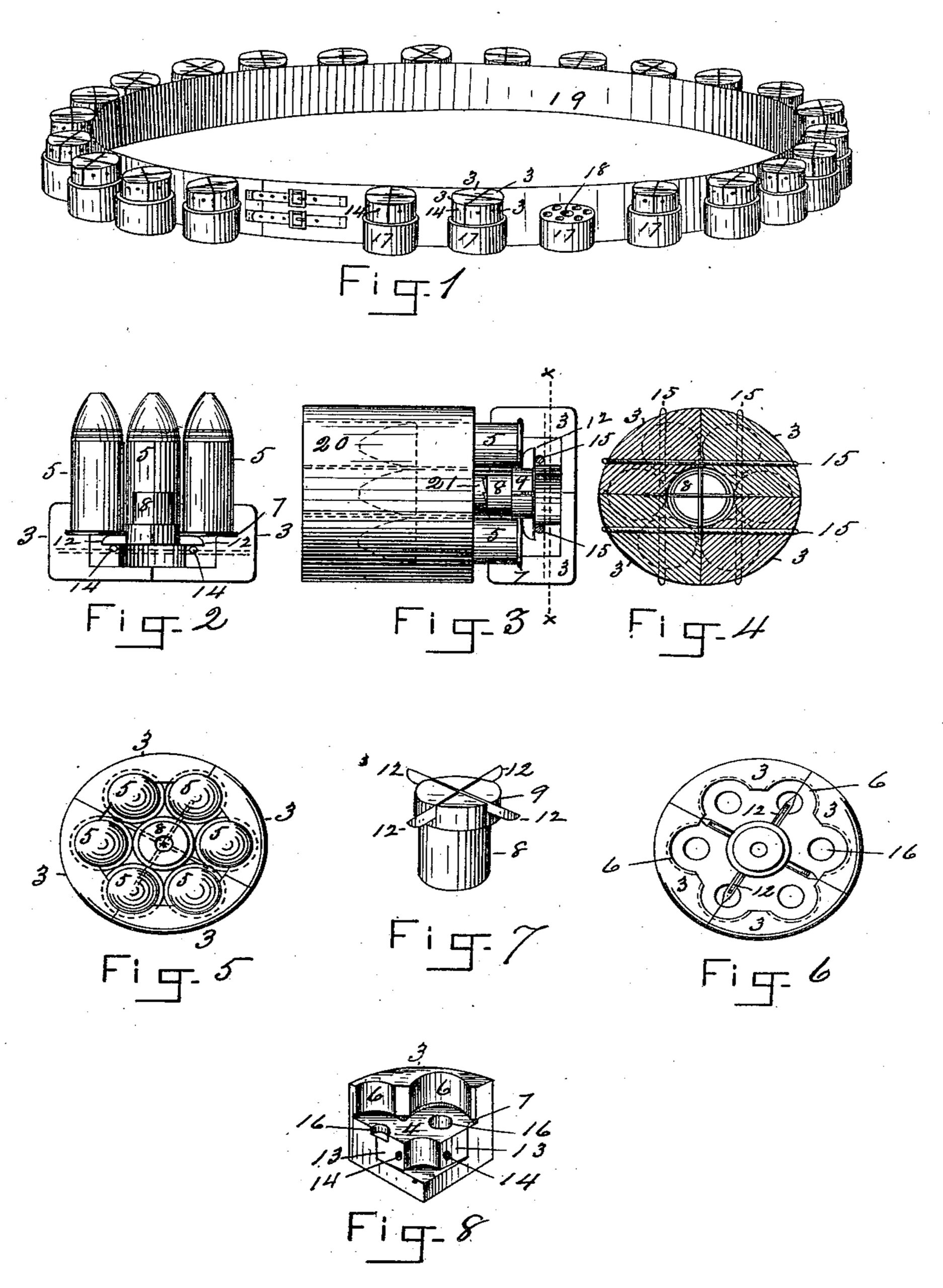
In the drawings forming part of this specification, Figure 1 is a perspective view of a eartridge-belt having connected therewith reloading-packs constructed according to my invention, one of said packs being shown removed from said belt, thereby illustrating the pack-block on the latter, which receives the points of the group of cartridges. Fig. 2 is a side elevation of a portion of one of, said reloading-packs. Fig. 3 is a side elevation of the cylinder of a revolving fire-arm, and of a portion of one of the reloading-packs, showing cartridges therein partially inserted in said cylinder. Fig. 4 is a transverse section of the casing of one of said reloading-packs on line x x, Fig. 3. Fig. 5 is a front elevation of one of the said packs. Fig. 6 is a front elevation of the pack-caging, including its cutter-plug. Fig. 7 is a perspective view of said plug. Fig. 8 is a perspective view of a segment of said casing.
In the drawings, 3 3 3 3 indicate segments of a casing, of wood preferably, but which may be made of any other suitable material, which segments, when united, as in Figs. 1, 4, 5, and 6, form a circular case, in one side of which is formed a chamber, 4, to receive the heads of such a number of cartridges, 5, as the pack may embrace, the number shown in the drawings being six. The borders of said chamber 4 have formed therein, vertically to the plane of the bottom of the latter, as many circular recesses 6 as is the number of cartridges that are to be placed therein,and the circular forms of said recesses correspond to that of the shells of said cartridges. At the lower ends of said recesses is formed a groove, 7, in which enter the rims of the heads of the cartridges, and whereby the latter are permitted to stand closely against the face of said recesses, and said rims thereby become so engaged with the said casing that they cannot drop out while the segments 3 thereof are held together and the cutter-plug 8 remains in the casing, as hereinafter set forth. A circular socket is made in the center of the chamber 4 in the said casing, a segment, 10, of whose wall is shown in Fig. 8, and the diameter of said socket is the same as that of the head 9 of the cutter-plug 8, said head 9 being of sufficient length to project above the bottom of said chamber 4, while its lower-end engages in said socket, as shown in Fig. 2, said plug being held in the position shown in said figure when the pack is completed, by the means hereinafter described, by which the several segments of the casing are united together and retained in the position indicated in Figs. 1 and 5; and when the cartridges are in the position shown in the latter figure in the casing their rims rest against the head 9 of said cutter-plug, whereby the opposite side of the rim is held within the said groove 7 at the bottom of the circular recesses 6 in the segments 3, and consequently the cartridges cannot drop out of the casing while the segments remain secured together.
It will be seen by reference to Figs. 2 and 3 that when the cutter-plug occupies the position there shown there is room at the base of the socket in which it is held to permit it to be moved endwise still farther into the latter. Said cutter-plug is provided with a series of cutters, 12, consisting of narrow strips of sheet-steel, having their edges sharpened, let into the end of the plug,and having their ends projecting from said head at four points, as shown. The meeting edges of the segments 3 are slightly cut away at 13, Fig. 8, to admit the.projecting ends of said cutters between the segments, as shown in Fig. 6, when the plug is in position in the case. Each of said segments 3 of the casing is provided with two transverse perforations, 14, which cross each other and coincide in position in the several segments, as shown in Fig. 4; and for the purpose of securing said segments together after the cartridges have been inclosed therein, a strong cord is drawn tightly through said perforations 14, which cords are indicated in Figs. 3 and 4 by 15, and they cross each other, as above set forth.
It will be seen in Figs. 2 and 3 that with the cutter-plug in the position above described, with its head between the group of cartridges, it holds the cutters 12 directly over said cords 15, so that an endwise movement of said plug, which shall drive the latter farther into its socket in the casing, must carry the edges of said cutters against the cords 15, cutting them off, and so separating the segments 3 that they are free to fall away from the group of cartridges. The base of the chamber 4 in said casing is provided with a series of shallow circular perforations, 16, over which the primers in the heads of the cartridges are brought when the latter are placed in the casing, thereby obviating any pressure upon the primers in transportation, and preventing accidental explosions of the same.
For the purposes of convenient transportation, and for carrying said reloading-packs about the person without danger of displacing either the cartridges or the segments of the casing inclosing the latter, a block, 17, of any convenient form, is provided, having in the end thereof a series of sockets, as shown, to receive the bullet ends of the cartridges of the pack and hold the latter, with the casing upward, in a convenient position to be grasped by the fingers, as indicated in Fig. 1. Said block 17, is provided with a central perforation, 18, which the small end of the cutter-plug 8 enters when the pack is carried on said block. In Fig. 1, 19 indicates a suitable belt, to which are secured, in any suitable manner, the said blocks 17, in which the said reloading-packs may be conveniently carried, said belt indicating only one of many devices that may be conveniently employed for the purpose above specified.
The operation of loading a revolving fire-arm by the use of the within-described reloading-pack is as follows: The cylinder 20, Fig. 3, represents substantially the cylinder of a pistol having on one end the usual ratchet projection, 21. When the pistol requires reloading, it is opened in the usual manner, thereby ejecting the empty shells and exposing the rear end of the cylinder in a convenient position to receive a charge of cartridges. The pistol being held in one hand, one of the reloading-packs (shown on the belt 19, or carried elsewhere) is grasped by the fingers of the other hand, taken from the block 17 and carried over the end of said cylinder, and the cartridges contained in said pack are inserted in the chambers of the latter, as shown in Fig. 8, and in moving the cartridges inward, by pushing the pack toward the cylinder, the end of the cutter-plug, as shown in said Fig. 3, is brought against the end of the ratchet 21 on the cylinder, and is thereby caused to slide rearwardly within the casing, thereby forcing the edges of the cutters 12 against the binding-cords 15 and cutting them all off simultaneously, thus detaching the casing-segments 3, and leaving them, together with the cutter-plug, free to drop away from the cartridges. The simple movement of the hand of the operator against the heads of the cartridges (provided they do not drop into the cylinder by gravity) completes the operation of loading the arm. The latter being then closed is ready to be fired, as usual.
The slight cost of the wooden segments forming the casing of the reloading-pack, together with the cutter-plug, makes it undesirable to save them after they have once served their purpose, as above set forth; but said parts may, if convenient, be collected and reused.
What I claim as my invention is—
1. A reloading-pack for fire-arms, consisting of a group of cartridges, a casing inclosing one end of said group, consisting of detachable segments united by severable connections, and cutting devices, substantially as described, for severing said connections, operated by the act of placing said cartridges in the fire-arm, substantially as set forth.
2. A reloading-pack for fire-arms, consisting of a group of cartridges, a casing inclosing one end of said group, consisting of detachable segments united by severable connections, having a chamber therein to receive the heads of said cartridges, provided with a groove around its border in which the rims of said heads engage, and, having a central socket therein, and a cutter-plug capable of an endwise movement in said socket, having cutters thereon extending between said segments and across said severable connections, substantially as set forth.
3. A reloading-pack for fire-arms, consisting of a group of cartridges, a casing inclosing one end of said group, consisting of detachable segments united by severable connections, having a chamber therein to receive the heads of said cartridges, provided with a groove around its border in which the rims of said heads engage, and having a central socket therein, and a cutter-plug capable of an endwise movement in said socket, having cutters thereon extending between said segments and across said severable connections, combined with a transportation-block for said pack provided with perforations to receive the exposed ends of said group of cartridges, and a central perforation opposite the end of said cutter-block, substantially as set forth.
DANIEL B. WESSON.
Witnesses:
WM. H. CHAPIN,
G. M. CHAMBERLAIN.