
US 542745
UNITED STATES PATENT OFFICE.
DANIEL B. WESSON, OF SPRINGFIELD, MASSACHUSETTS.
LIMITING-STOP FOR REVOLVER-CYLINDERS.
SPECIFICATION forming part of Letters Patent No, 542,745, dated July 16, 1895.
Application filed February 23,1895. Serial No. 539,379. (No model.)
To all whom it may concern:
Be it known that I, DANIEL B. WESSON, a citizen of the United States, residing at Springfield, in the county of Hampden and State of Massachusetts, have invented new and useful Improvements in Revolving Firearms, of which the following is a specification.
This invention relates to revolving firearms, the object being to provide improved means for the engagement of the cylinder with the frame of the arm, whereby the cylinder is more firmly held against either a forward or a rearward movement; and the invention consists in the improved means for so holding said cylinder, all as hereinafter fully described, and more particularly pointed out in the claims.
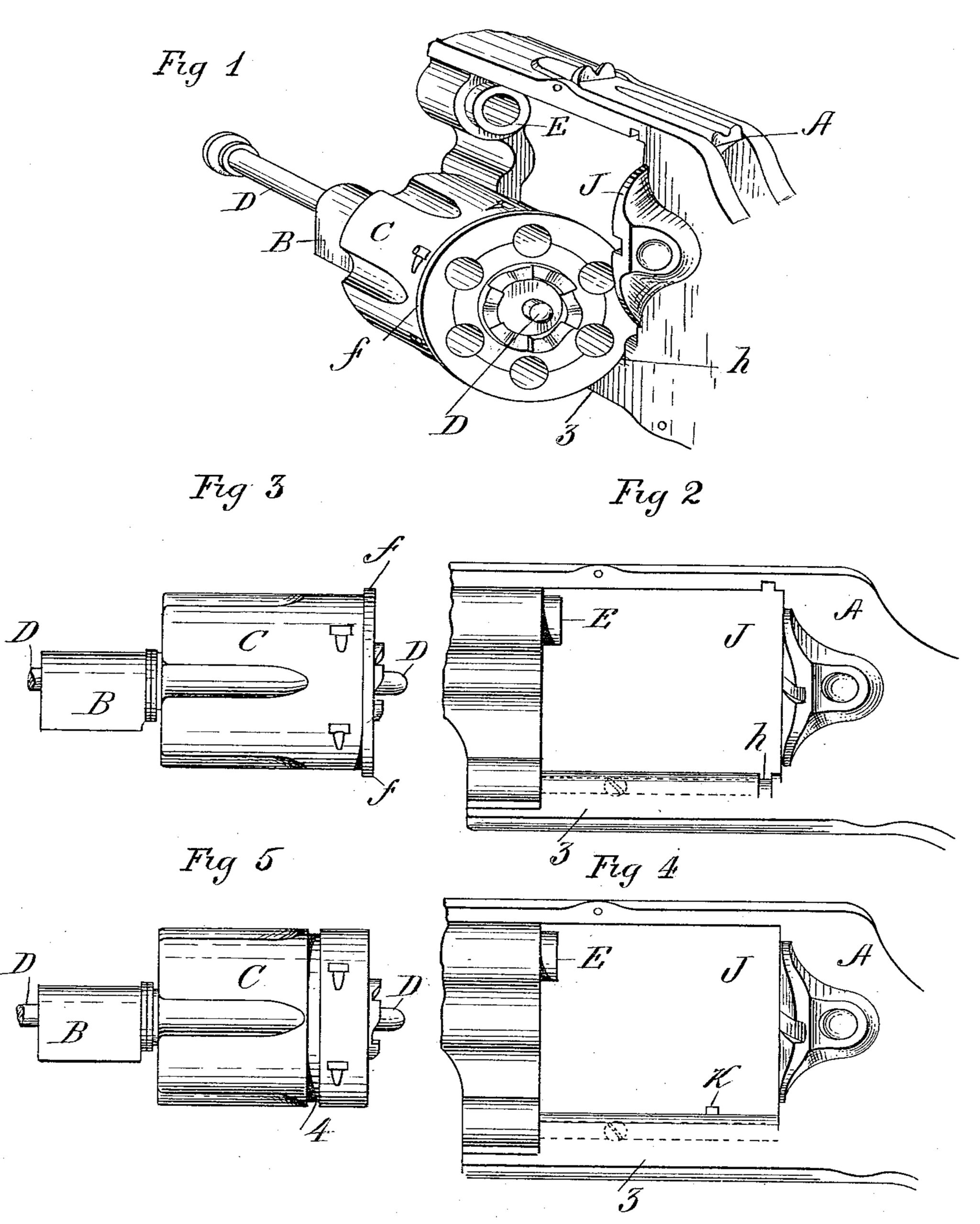
In the drawings forming part of this specification, Figure 1 is a perspective view of the cylinder and a portion of the frame of a revolver embodying my improvement and of that class of arms in which the cylinder is hung upon a yoke which swings in the frame to carry said cylinder to one side and sufficiently out of said frame to permit of ejecting empty cartridge-shells and reloading the cylinder. Fig. 2 is a side elevation of said part of the frame of the arm, and Fig. 3 is a like view of the cylinder. Figs. 4 and 5 are side elevations, respectively, of a frame part and cylinder, illustrating a modification of the construction of the cylinder-holding devices shown in the preceding figures.
In the drawings A indicates that part of the frame of a revolver to which the cylinder is connected.
B is a part of the swinging yoke-frame, on which the cylinder C is supported, said yoke-frame having an arm, on which it swings, entering a socket (shown in dotted lines) in the part of said frame under the cylinder-opening therein, and a second arm or “ base-pin,” as generally termed, on which the cylinder rotates, all as shown in detail and described in my Patent No. 517,152, dated March 27, 1894.
The cylinder-locking pin D has a longitudinal movement within the cylinder, its rear end engaging in a socket in the frame to lock the cylinder in firing position when swung into the frame. E indicates the rear end of the barrel in the frame.
The aforesaid cylinder-locking improvements are constructed and arranged as follows: The cylinder C has a border f around its rear end, projecting beyond the plane of the outer surface of the cylinder, and a groove is made in and across the part 3 of the frame A under the cylinder, which groove receives the said projecting border or flange f on the cylinder when the latter is hung on its yoke-frame B, as in Fig. 1. The thickness of said border or flange f and the width of said groove h are such that the cylinder may, while said flange is in engagement with said groove, rotate freely. No perceptible movement of the cylinder may take place either toward or from the recoil-plate J. Thus in the act of firing the arm the cylinder is provided with additional means of resistance against the tendency to forward movement or one from the recoil-plate induced by the explosive force of the charge when firing. When the cylinder and cylinder-supporting frame are swung to the side of the arm, as in Fig. 1, this being the position for extracting the spent cartridge-shells and for loading the cylinder, the rim or flange f on the cylinder extends into the groove h in the frame and the cylinder is firmly held against front or rear movement and the side swinging frame is greatly relieved from strain. In some classes of arms said additional means of resistance against the tendency of the cylinder to move away from the recoil-plate aids in preventing the bursting of the heads of the cartridges and contributes generally to safety and convenience in the use of the arm. The said modification illustrated in Figs. 5 and 6 consists in providing a circular groove 4 in the cylinder and in providing a fixed projection K on the frame, which when the cylinder is in the latter engages in said cylinder-groove. In the above described modification substantially the same operative results are secured as those pertaining to the construction illustrated in Figs. 1 to 3, inclusive.
The within-described devices for holding the cylinder of a revolving firearm, as described, are in the nature of an improvement upon the device patented to Trabue, No. 301,180, dated July 1, 1884. A device similar to Trabue’s is also shown in Fig. 7 of patent to Warnant, No. 301,649, dated July 8, 1884; but the latter-named device is objectionable, since the rear end of the cylinder would bear against the projection there shown during its entire swinging movement, making it hard to swing it and impossible if the cartridges should swell on explosion.
Having thus described my invention, what I claim, and desire to secure by Letters Patent, is—
1. In a revolving fire arm, the frame, a yoke supported in the frame and swinging to the side of said frame as described, and the cylinder supported on said yoke, and having a projecting rim near its rear-end which enters a groove in the frame, substantially as described.
2. In a revolving fire-arm, the frame, a yoke supported in the frame and swinging sidewise, the cylinder supported on said yoke, said frame and cylinder having interlocking projections which engage and prevent longitudinal movement of the cylinder in both directions when swung outward to the side of the frame, substantially as described.
3. In a revolving fire arm, the frame, the cylinder supporting yoke pivoted in the frame so as to swing sidewise therein, and the cylinder carried by said yoke, said cylinder and frame having interlocking projections which engage the periphery of the cylinder with the frame and hold the cylinder against longitudinal movement in both directions and thereby relieve the yoke, substantially as described.
DANIEL B. WESSON.
Witnesses:
H. A. CHAPIN,
K. I. CLEMONS.