
US 158874
UNITED STATES PATENT OFFICE.
DANIEL B. WESSON, OF SPRINGFIELD, MASSACHUSETTS.
IMPROVEMENT IN REVOLVING FIRE-ARMS.
Specification forming part of Letters Patent No. 158,874, dated January 19, 1875; application filed
July 30, 1874.
To all whom it may concern:
Be it known that I, DANIEL B. WESSON, of Springfield, in the State of Massachusetts, have invented a new and useful Improvement in Revolving Fire-Arms; and I do hereby declare that the following is a full, clear, and exact description thereof, reference being had to the accompanying drawing making a part of this specification, and to the letters of reference marked thereon, in which—
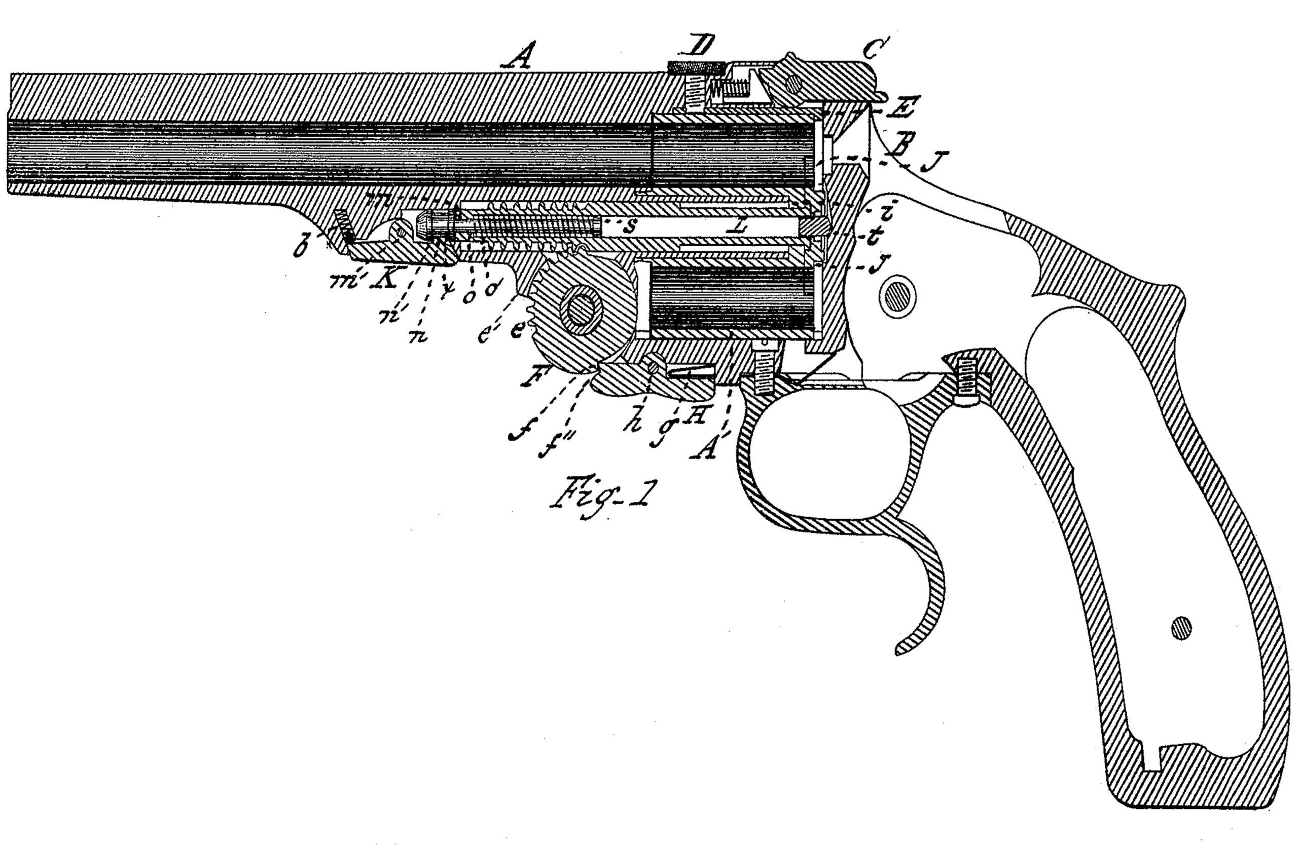
Figure 1 is a central vertical longitudinal section through a revolving fire-arm, showing
my invention applied thereto.
My invention relates to that class of revolving fire-arms, in which a many-chambered cylinder is made to revolve at the rear of the barrel, and in which an extracting-plate, having a stem extending through said cylinder, is used to extract the empty shells from the rear of the chambers of the cylinder; and my invention consists, first, of a rod, arranged to slide within the hollow stem of the extractor, the latter having a shoulder inside, near its forward end, and the rod a shoulder at the rear end, between which shoulders a spring, arranged upon the rod, has its bearings, and the rod has an annular shoulder at the forward end, against which a hook or catch engages to draw out the sliding rod, when the extractor-stem is moved to the rear, and also to prevent the rod from sliding into the stem, when released from its catch; and my invention consists, second, of a finger-piece or lever, pivoted to the frame beneath the cylinder, and having a part thereof projecting below the lower surface of the frame, so that it may be easily pressed upward by the finger, and having upon its forward end a shoulder, which abuts against a shoulder in the idler, and which has also upon its forward end an incline, which, when the forward end of the barrel is moved downward upon its pivot to its fullest extent, rides over a point or abutment beneath the barrel, and moves the forward end of the finger-lever from contact with the idler, and permits the latter to turn back upon its pivot.
In the drawings, A represents the barrel, B the frame, and A’ the chambered cylinder, made to revolve in the frame at the rear of the barrel. L is the extractor-stem, which is made hollow, and into which is inserted from the rear end the rod m having a spring, o’, thereon, which bears against a shoulder, o, made on the inside of the hollow stem L at its forward end, and against a shoulder, s, made on the rear end of the rod. A head is attached to the forward end of the rod, which has a shoulder, x, to limit the inward movement of the rod m, and also an annular shoulder, n’, against the rear side of which the hook or catch n, made on the rear part of the lever K, engages. This lever K is pivoted to the under side of the frame, and a spring, b, inserted in its recess, operates to force out the forward end of the lever, keeping the projection or catch m on the rear part always in against the annular shoulder n’, and the rear end of the lever K and the forward end of the rod m are so beveled as to permit the rod to slide over the catch n whenever the rod is forced forward into place. The toothed idler F is pivoted in the joint in the ordinary manner, and the extractor-stem has the annular teeth or projections to correspond, by means of which the extractor is moved to the rear in the cylinder to extract the shells; and to the under side of the frame is pivoted the lever H, which has a shoulder, f’, on the upper part of its forward end, to abut against a corresponding shoulder made in the idler, and which has also an incline, f”, on its lower forward end, so arranged as to ride up upon the
part e’ of the lower portion of the barrel, when the forward end of the latter is forced downward to the proper extent in raising the rear end of the cylinder. A spring, g, is arranged between the rear end of the finger-lever H and the frame, to keep the forward end of the lever always pressed in against the idler, and some part of the rear arm of said lever projects outward beyond the under side of the frame, so that said lever may be easily pressed in by the finger, by which the forward end of the lever may be disengaged from the idler.
The operation of my invention is as follows: The arm having been discharged, the latch C is thrown upward, unlocking the barrel from the frame, and the forward end of the barrel is tilted down. As this movement is made, the idler F is prevented from rotating by the finger-lever H, and the annular teeth upon the extractor-stem engaging with the teeth of the idler the extractor-plate and stem are moved through the cylinder to the rear to throw out the shells. As the catch n on the lever K, however, remains in contact with the annular shoulder n’ on the end of the rod m, the latter is prevented from moving with the extractor-stem, and is drawn partially out of the latter, thereby compressing the spring o’ upon the rod m and within the stem until, as the barrel is tilted farther down, the point e’ passes under the incline f” at the forward end of the finger-lever H, throwing out that end of the lever, and disengaging it from the shoulder on the idler. As the idler is thus released the elasticity of the spring operates to draw forward the extractor-stem and rotates the idler, and the extractor and stem quickly fly back to place. The extractor being then in place against the rear end of the cylinder the loaded shells may then be inserted into the chambers, and the barrel being then tilted up into place the end of the finger-lever H rides around on the smooth periphery of the idler until it is forced, by the spring g, into place in contact with the shoulder f.
If it is desired to detach the cylinder and extractor from the barrel the thumb-screw D, at the top of the barrel, is turned out sufficiently to release the cylinder-catch E, and the barrel being unlatched from the frame the forward end of the lever or detent K is pressed upward with the finger, detaching the catch n from contact with the shoulder n’ on the end of the rod m, and the cylinder and extractor may be then removed. When replaced the beveled end of the rod m as it is being moved into place slides over the catch n, which quickly springs into place behind the shoulder n’. The cylinder-catch is then inserted in place, the thumb-screw D turned in, and the arm is ready for use.
Sometimes it is desirable to tilt down the barrel without having the extractor move to the rear—as, for example, if one or more of the cartridges should be faulty, and it should be desired to tilt down the barrel without having the cartridges moved out. In that case it would only be necessary to unlatch the barrel from the frame and press up the rear end of the lever H with the finger, as the rear end of the barrel is started upward, thereby releasing the forward end of the said lever from the idler. The extractor will not then be thrown out, and the barrel may then be tilted down without moving the extractor until the rear end of the cylinder is brought down into position to be latched to the frame, allowing the forward end of the finger-piece H to drop into place behind the shoulder f on the idler, when the extractor will operate as before.
As a part of the finger-lever H projects below the surface of the lever part of the frame, to which it is attached, it will be seen that said lever, and the movement of the extractor, may be easily operated by the presence of the finger of the same hand which holds the pistol, while the other hand is used to manipulate the cartridges.
I am aware that catches of various designs have heretofore been used to retain the idler in place while extracting the shells; but I am not aware that the device hereinbefore described has ever before been made or used:
Having therefore described my invention, what I claim as new is—
1. The combination of the detent K, held in place by a spring-rod, m, spring o’, and extractor-stem L, substantially as set forth.
2. A finger-piece, H, pivoted about midway its length, a part of which projects below the surface of that part of the frame to which it is attached, so that it may readily be operated by the pressure of the finger to disengage it from the idler, and also provided with an incline, f”, to ride up upon a projection on the lower part of the barrel, in combination with an idler for operating the extractor.
3. The combination of the hollow extractor-stem L, spring-rod m, and spring o’, substantially as described.
DANIEL B. WESSON.
Witnesses:
T. A. CURTIS,
C. E. BUCKLAND.