
US 51752
UNITED STATES PATENT OFFICE.
JAMES REID, OF CATSKILL, NEW YORK.
IMPROVEMENT IN REVOLVING FIRE-ARMS.
Specification forming part of Letters Patent No. 51,752, dated December 26, 1865.
To all whom it may concern:
Be it known that I, James Reid, of Catskill, in the county of Greene and State of New York, have invented, made, and applied to use a certain new and useful Improvement in Revolving Fire-Arms; and I do hereby declare the following to be a full, clear, and exact description of the same, reference being had to the annexed drawings, making part of this specification, wherein—
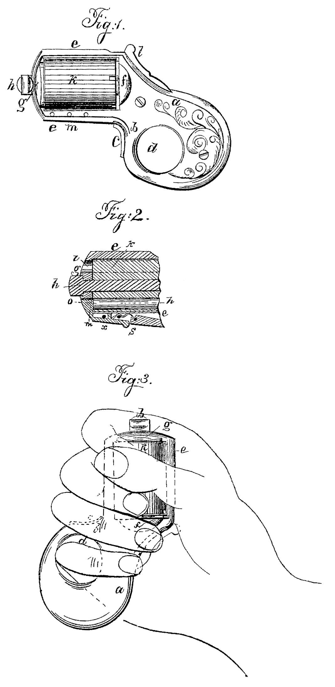
Figure 1 is a side elevation of said fire-arm. Fig. 2 is a section through the forward end of the frame and barrels, and Fig. 3 represents. the piece as grasped in the hand as a means of a defense, should the same be used in that manner instead of being fired.
Similar marks of reference denote the same parts.
My invention is applied to a series of short barrels mounted on a center-pin in a frame. Said invention consists in a sliding stop fitted in said frame so as to take the forward end of one of the barrels when the barrels are not required for use and are turned for safety, so that the hammer rests upon the metal between two of the barrels; and I form the handle with a bow behind the trigger-shield, so that the implement may be held securely in the hand and used for protection after the barrels may have been discharged, or before it becomes necessary to use them.
In the drawings, a represents the handle of my revolving fire-arm.
b is the shield, containing the trigger c, and this shield and the handle a are connected so as to form a bow or ring, d, through which the finger may be passed when the piece is grasped, (as seen in Fig. 3,) so as to be used in hitting a blow for self-protection before using the bullet, or after the revolver has been fired.
The frame e extends out from the recoil-shield if on the end of a, and said frame e is provided with the end. shield or cap-piece, g, through which the center-pin h passes, and is screwed in, as seen in Fig. 2, the back end of the pin h passing into a hole in the center of f. Upon this pin h the barrels k are mounted, and each of the barrels is formed with an opening through to the rear, and each barrel is enlarged near the back end for a sufficient distance to allow for the introduction of a cartridge-case containing ball, powder, and fulminate, as usual.
The barrels can be easily taken out for loading by unscrewing the pin h, and the loading is effected by introducing the cartridge in a suitable case into the rear end of each barrel.
The hammer l is fitted in any usual or well known manner with a pawl to take ratchet-teeth at the rear end of the barrels and rotate them, and with a cam to act upon a locking-lever that operates in the lower part of the frame e, as now usual.
The end shield, g, covers up all the barrels k except the one on line with the hammer, an opening, as at i, Fig. 2, being provided for the ball to pass out when the piece is fired.
The loading and firing of the piece will be apparent from the foregoing; but when it is desired to lock the piece so that it cannot be accidentally discharged I employ the sliding stop m, that is placed in a groove in the under side of the frame e and front of the shield g, having a circular projection, o, fitting one of the barrels in k. When the barrels k are turned so that the end o can be slid into one of the barrels and prevent them from turning, then the upper barrels will not be on line with the hammer, but one of the divisions between said barrels will be on line, (there being an odd number of barrels,) so that an explosion cannot take place, and the barrels cannot be revolved. Hence the arm is useless until the barrels are liberated by sliding the stop m forward.
The stop m is retained by a pin passing into a slot or notch, as seen at x, Fig. 2, and a spring, s, is employed to prevent said stop m sliding accidentally, the end of the said spring s taking into notches in m, as seen in Fig. 2.
What I claim, and desire to secure by Letters Patent, is—
1. The sliding stop m o, fitted as specified, in combination with the frame e g and barrels, for the purposes and as specified.
2. Connecting the trigger-shield b and handle a so as to form the bow d, for the purposes and as set forth.
In witness whereof I have hereunto set my signature this 18th day of September, A. D. 1865.
JAMES REID.
Witnesses:
Thos. Geo. Harold,
Chas. H. Smith.