
US 102782
UNITED STATES PATENT OFFICE.
CHARLES FELIX DE DARTEIN AND JULES EDOUARD DE DARTEIN, OF STRASBOURG, FRANCE.
IMPROVEMENT IN REVOLVING FIRE-ARMS.
Specification forming part of Letters Patent No. 102,782, dated May 10, 1870.
To all whom it may concern:
Be it known that we, CHARLES FELIX DE DARTEIN and JULES EDOUARD DE DARTEIN, of Strasbourg, in the Empire of France, have invented a new and Improved Fire-Arm; and we do hereby declare that the following is a full, clear, and exact description thereof, which will enable others skilled in the art to make and use the same, reference being had to the accompanying drawings, forming part of this specification.
This invention relates to an improvement in revolving fire-arms; and it consists, chiefly, in a novel mode of actuating and stopping the revolving cylinder. The revolving cylinder is set in motion or locked by means of portions of helices which we call “winglets” or “lugs,” of which there are as many as there are bores in the revolving cylinder. These lugs are arranged symmetrically on the exterior periphery of the revolving cylinder, and are actuated by a sliding bolt that is connected with the sliding hammer. The bolt has a spring, click, or pawl which yields to the lugs while the bolt is moving forward, while it becomes rigid to move them and turn the cylinder during the backward movement of the bolt.
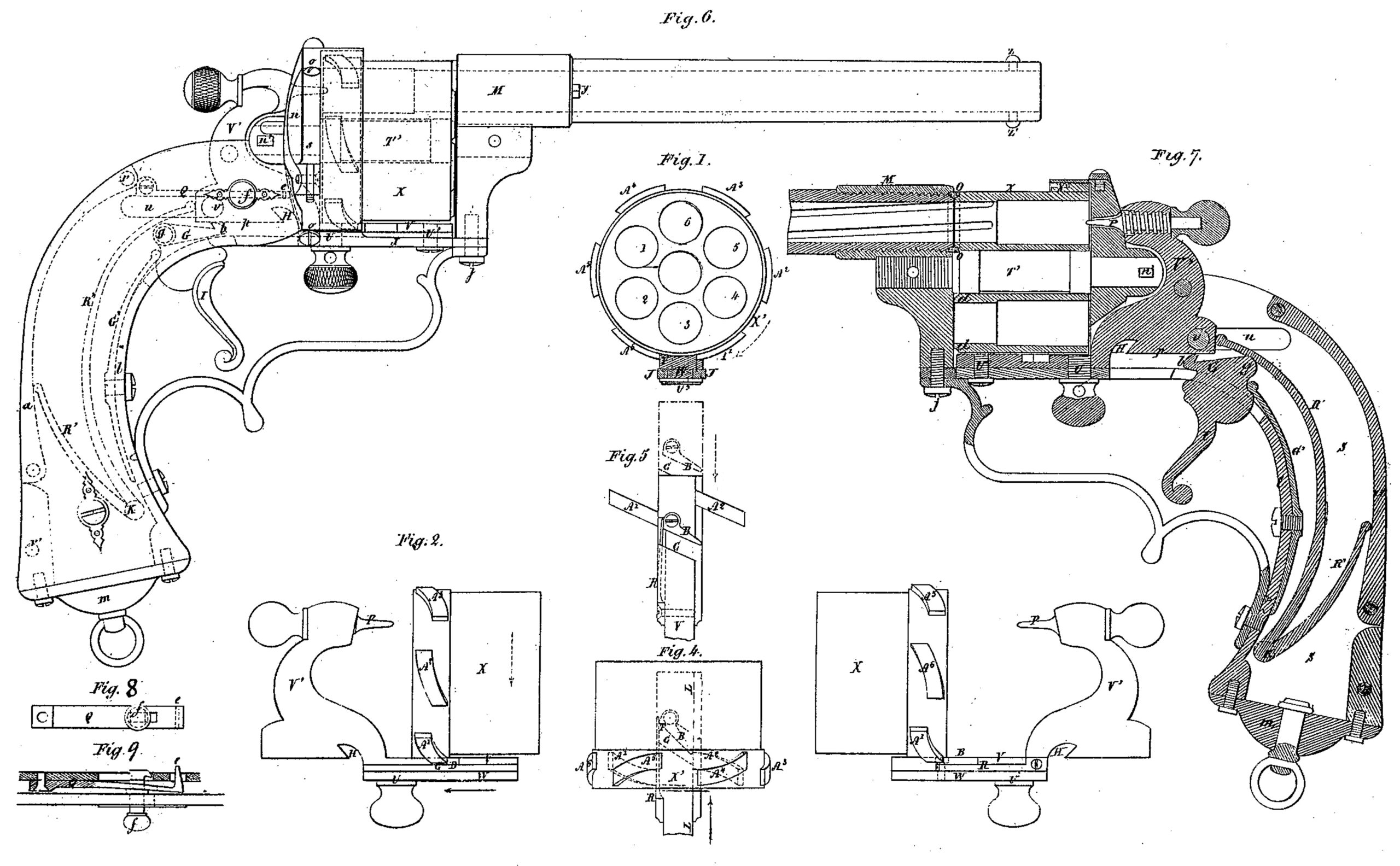
In the accompanying drawings, Figure l represents a back view of the cylinder, with its bolt in section. Fig. 2 is a right-hand-side view of the same, the bolt being about cocking. Fig. 3 is a left-hand-side view of the same, showing the piece after cocking. Fig. 4 is a plan view of the same. Fig. 5 is a plan view of the bolt and click, the dotted lines showing the position of the click after discharge. Fig. 6 is a side view of the pistol. Fig. 7 is a longitudinal section of the same. Figs. 8 and 9 are separate views of the safety-stop.
Similar letters of reference indicate corresponding parts.
X is the revolving cylinder of a suitable fire-arm. The cylinder X is provided on its exterior periphery with portions of helices or lugs A’ A2 A3 A4 A5 A6 corresponding to the number of chambers in said cylinder. Between these lugs is arranged, on the lower arm of the stock, a sliding bolt, V, which has a groove, G, across it. This groove is parallel with the lugs A’, so as to let the latter pass while the cylinder X is rotating. To the bolt is pivoted a click, B, with a spring, R. This click B folds down, so as to pass under the lugs A while the bolt V is moving forward, and then immediately becomes rigid, being acted upon by its spring R, SO as to carry along the following lug as the bolt moves backward. Thus by cocking the click B, being pushed in the direction of the black arrow, Fig. 2, catches the lug A’, for instance, and causes it to pass on the opposite side of the bolt, thereby imparting a rotary motion to the cylinder in the direction of the dotted arrows, Figs. 1 and 2, the degree of motion being such as to make the axis of the chamber A’ in this instance coincide with that of the long barrel.
The bolt V, which forms part of the hammer V, is held back by a tumbler, G, which falls into the notch H provided for it. By moving the trigger I the tumbler is withdrawn, the bolt is forced forward by its spring R. A pin, P, secured to the hammer, enters the upper chamber of the cylinder and ignites the fulminate, discharging the cartridge that is inserted in the breech of the chamber A’. During the forward motion of the bolt the click B has passed under the lug A, which will force it to yield or deflect along the line I, L. When the lug A has been passed the click will rise again, under the action of the spring R upon its tail T, and will assume the position shown in dotted lines, Fig. 5. It is then ready to catch the lug A2, the same as it did A’, &c., for every following cartridge.
Figs. 6 and 7 show the application of our system to a pistol, as well as some general improvements applicable to fire-arms. The pistol comprises a barrel, a cylinder, a bolt, with its spring, a tumbler-trigger, with its spring, and a safety-stop. The whole of these pieces are mounted on a stock made partly of metal and partly of wood. We shall now proceed to describe the various portions of the arm. The barrel is of the ordinary description, either rifled or smooth, and carries two opposite sights, Z, Z’. The barrel is secured by a screw-thread in the ferrule or union M, which forms part of the pistol-shaft. The operator may, by a mere effort of his hand, or by using the head of the ramrod, which acts as a key, give the barrel one half-turn to the right or left, the object of which is to bring the cylinder nearer to or farther from the back facing of the barrel. Upon the facing of the cylinder there is or may be a conical projection, d, at each chamber, corresponding in form to a ring, O, of leather, india-rubber, or any other elastic material, secured to the breech end of the barrel, so as to slightly overlap the same. When, by the semi-rotation imparted to the barrel from left to right, the latter facing closes upon the facing of the cylinder the ring O slips over the conical burr of the chamber opposite the barrel, and forms a gas-tight joint between the two. Escape of gas is thus entirely obviated; but however advantageous this result may be, it necessitates a double motion of the barrel for each shot fired. If, therefore, the extremely tight joint is no object, and quick firing be required, the operator may use the sight Z’. Two stops, Y, placed one on each side of the barrel, are used for maintaining the barrel in either of its two positions.
The cylinder X has six bores or chambers, but this number may vary, and a central bearing for the spindle T’, on which it revolves. The cylinder X is provided at its back part with a ferrule or hoop, X’, carrying the lugs, or winglets A’ A6, and this ferrule is secured by screws.
The chambers of the cylinder may have grooves of rifling to correspond exactly with the grooves of the barrel, if the latter be rifled.
Under the bolt V there is a sole or rail, W, sliding in a guide-slot, J, in the under piece of the stock. This rail is secured to the body V by two screws, U U’, which serve at the same time to keep the bolt in the slot J, the first one, U, having a bolt-head, so that the finger of the operator may catch it while cocking and uncocking.
The bolt V is pushed forward by a spring, K’, mounted on the two tenons K, and having two arms or branches of an equal elasticity, the shorter one bearing against the back a of the stock-mounting, and the longer one against the tail of the bolt, thus tending to push the latter forward with sufficient impetus to fire the priming of the cartridge. The firing-pin P is screwed into the upper portion of the bolt hammer appendix V’, so that if the user of the arm wants to render the firing of the cartridges a matter of absolute impossibility he need only move the needle back of the breech-facing by merely unscrewing.
The piece G performs the part of both the tumbler and trigger now in use. It is pivoted on the gudgeon g, and its nib b is forced against the foot p of the hammer W by the spring G’ acting on its tail.
The safety-stop is a mere spring, Q, having a nib, e, projecting inside the mounting, but is covered in with wood, so that the knob f alone shall be visible outside. When left to its own tendency the spring will stand up, so that the nib e shall not pass beyond the inside of the mounting, and thus will not impede the travel of the bolt. In order to use this safety arrangement the operator has to pull the bolt back with his forefinger, bearing at the same time with his thumb upon the knob f, thus causing the nib e to project inside, then letting go the bolt he allows the same to advance and become engaged with the nib e, which keeps it in place, while at the same time the pressure of the spring R’ upon the bolt prevents the said nib re-entering its place. The operator then wishing to fire pulls the bolt V back to the compressed or tension state, and the nib e of the spring Q being then released the latter will of itself retire to its place, offering no longer an obstacle to the discharging motion of the bolt V; but in order that the bolt V may not shoot forth accidentally –i. e., without the will of the wearer of the weapon– we employ the button f, which is caught by the spring Q, may slide in it and hook onto the plate carrying the spring, thus paralyzing the tendency of the latter toward recoiling.
The loading can be effected from the back end of the cylinder when ordinary cartridges are used. To this effect a door or gate, s, is arranged in the breech u, which is kept either open or shut by the pressure of a small spring on a tail or projection near its hinge. Instead of one gate only, two may be used. We may also add that all the parts of the mechanism subject to wear –such as the tail, the foot, the sole, and the pins of the bolt, the lug, ferrule, or hoop of the cylinder, &c.– will in the course of manufacture form small pieces, which can be at once fitted on the main pieces by screwing or pinning, so as to be easily replaced.
The invention is equally applicable to pistols, muskets, rifles, &c., the details of construction being necessarily modified in accordance with the nature of each arm.
Having thus described our invention, we claim as new and desire to secure by Letters Patent
1. In combination, with the cylinder X, provided with helical lugs, the bolt V, having click B and spring R, the hammer V’, tumbler G, trigger I, and spring B, all arranged to operate substantially as shown and described.
2. The sliding bolt V, grooved to correspond with the helical lugs, and provided with a click, B, and spring R, for the purpose of imparting intermittent rotary motion to the cylinder, as set forth.
C. F. DE DARTEIN.
JULES DE DARTEIN.
Witnesses:
JOSEPH. BERGER,
CH. BROOHPIN,
C. M. FELIX PETARD, U. S. Consul.