
US 85350
UNITED STATES PATENT OFFICE.
JOHN ADAMS, OF THE STRAND, ENGLAND.
IMPROVEMENT IN REVOLVING FIRE-ARMS.
Specification forming part of Letters Patent No. 85,350, dated December 29, 1868; patented in England, July 28, 1866.
To all whom it may concern:
Be it known that I, John Adams, of the Strand, in the county of Middlesex, England, have invented certain Improvements in the Construction of Breech-Loading Revolver Fire-Arms; and I do hereby declare that the following is a full and exact description thereof.
My said invention consists in certain improvements in breech-loading revolver fire-arms, whereby great simplicity of construction is combined with efficiency of action.
In constructing breech-loading revolver fire-arms in accordance with my said invention, I take a forging of iron or steel which has been reduced roughly to the form of the barrel of the revolver fire-arm, and the solid frame to contain the revolving cylinder, and I bore the barrel from end to end, and also bore a small hole at the back of the cylinder-frame concentric with the bore of the barrel. This small hole serves to fix the barrel to the machines which may be used in course of manufacture, and also to admit the nose of the hammer to the center of the cartridge. After the barrel is reduced to the required shape and dimensions and the space cut out of the solid frame to receive the cylinder, I cut away, by means of circular cutters or other suitable tools, from the bottom and rear end of the frame spaces to receive portions of the lock. I then take a breech or back piece and cut away from the center thereof, by means of circular cutters or other suitable tools, sufficient metal to receive with accuracy the lower part of the frame. In the center of this space I cut away still further (also by means of circular cutters or other suitable tools) a smaller space, of the necessary. Width and depth to receive the hammer and the top strap which secures the stock in its place.
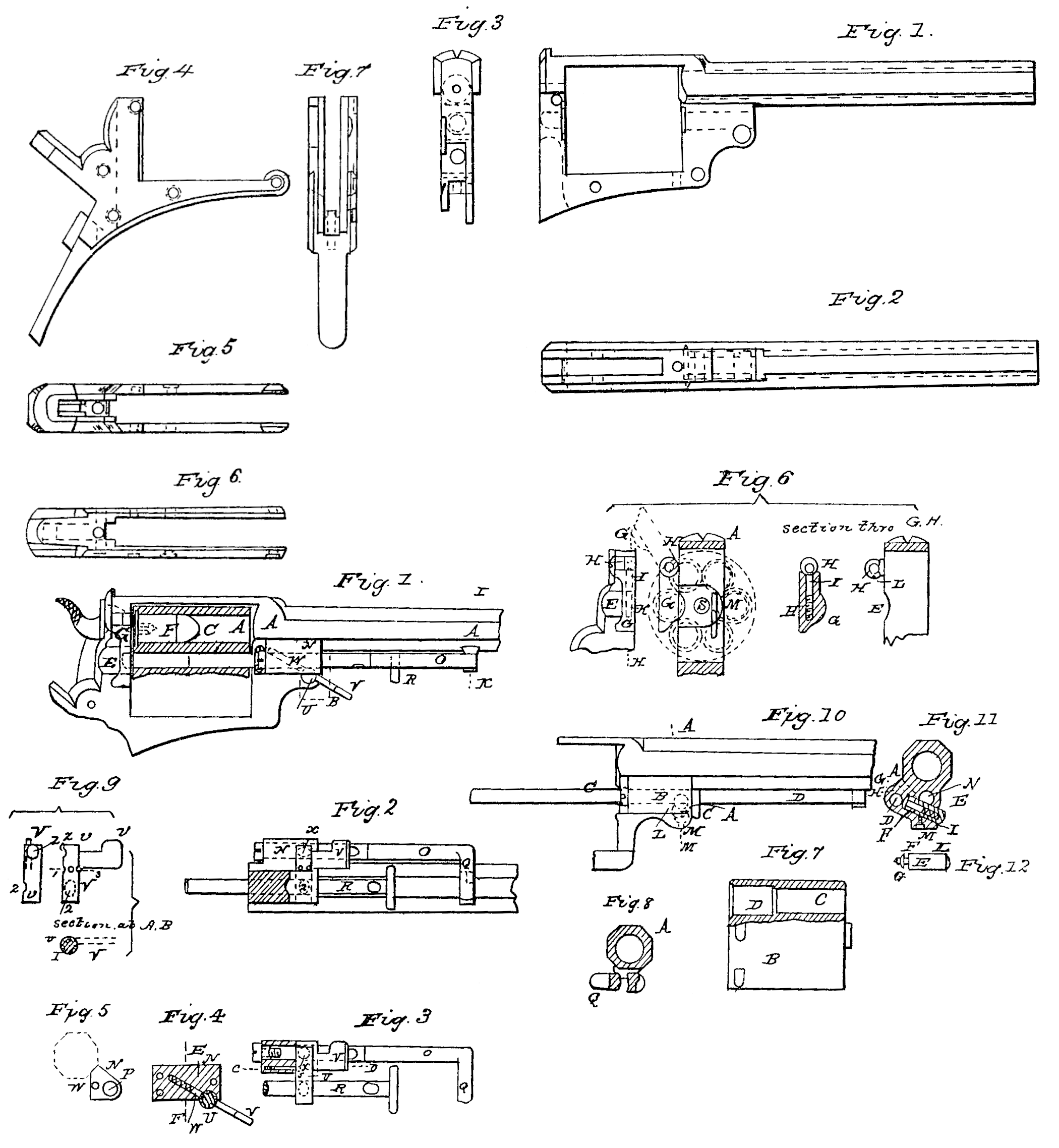
In Sheet 1 of the annexed drawings, Figure 1 is a side view, Fig. 2 a bottom view, and Fig. 3 a back view of the barrel and frame. Fig. 4 is a side view, Fig. 5 a top view, Fig. 6 a bottom view, and Fig. 7 a back view, of the breech or back piece.
A cylinder is introduced into the frame, the chambers of such cylinder being drilled through the same from end to end, and the back part of each chamber being made larger to the length of the cartridges than the front part thereof. This enlargement is parallel, and does not taper in any way, excepting at the front end, so as to allow the ball to pass over freely into the smaller part of the chamber. On the side of the frame, at the rear end of the cylinder, a sufficient quantity of metal is cut, away to allow the cartridges, which are of the description known as “central-fire” cartridges, to be inserted into each successive chamber as the cylinder is rotated. To prevent the cartridges from falling out through the opening thus cut away, a small shield is attached to the frame by means of a hinged joint, which shield fits into the above-mentioned opening, and when closed prevents the cartridge from falling out. The shield, when closed, is kept in its position by means of a small bolt and a spiral spring, which are inserted into a hole drilled into the shield. One end of the bolt is coned, and when the shield is closed is forced by the spiral spring into a small recess adapted to the shape of the coned end, which recess is cut into that portion of the hinged joint of the shield which is fixed to the frame. The shield is thus held in its position when down, and by pressing the shield upward with the finger the coned end of the bolt slips out of the recess and allows the shield to be turned up when it is desired to free the opening above described.
The fixed shield ordinarily employed it revolver fire-arms is entirely dispensed with, a, portion of the chambers of the cylinder, when on the side of the frame opposite to that on which the movable shield is placed, being partially covered by the rear end of the frame, whereby the cartridges are prevented from falling out. By means of this arrangement it is also readily seen when the chambers are loaded, such chambers not being hidden by any shield attached to the frame, as in the methods of construction ordinarily adopted.
Attached to the frame of the barrel,in front of the cylinder, is a piece of metal, having a hole drilled through the same for the purpose of receiving a movable rod, which works there in in a line with the opening in the frame above described, in which the cylinder is placed. This rod is for the purpose of pushing out the cartridges before, or the cartridge-cases after, the revolver has been fired, and is called the “ejector,” the hole through which it passes being called the”ejector-hole.” The end of the ejector which is farthest from the cylinder is turned at a right angle, or nearly so, and when in its normal position lies under the barrel.
The cylinder-rod runs parallel with the ejector through a hole cut through the frame; and in order to keep both in their normal positions when the revolver is ready for firing, a hole is drilled through a portion of the frame in front of the cylinder, the same cutting partially into the ejector and the cylinder-rod, and also into the piece of metal which carries the ejector. Into this hole is inserted a bolt, having for its object the locking both of the ejector and the cylinder-rod when in their normal positions. This bolt, which may be termed the “primary” bolt, is fitted to the hole, and has a thumb-piece attached to it for the purpose of turning it round. The thumb-piece, when both the ejector and the cylinder-rod are in their normal positions, lies flat against the piece of metal which carries the ejector. It is kept in that position by means of a spiral spring and a bolt similar or analogous to that described above as being inserted into the movable shield. This spring and bolt (which latter may be termed the “secondary” bolt) may either be inserted into the piece of metal which carries the ejector, or into the frame itself, and the coned end thereof, when the primary bolt is closed, is forced into a recess cut into the primary bolt. When it is desired to release the ejector the primary bolt is, by means of the thumb-piece above described, turned practically round until the coned end of the secondary bolt drops into a second recess, cut also in the primary bolt. When this is done a third recess, cut into the primary bolt, and corresponding in size and form with that portion of the ejector-hole otherwise occupied by the primary bolt, is brought opposite to such hole. The ejector is thus released. When it is desired to lock the cylinder the ejector is pushed into one of the chambers until the second recess in it comes opposite the primary bolt. The primary bolt is then turned until the thumb-piece lies flat against the metal piece which carries the ejector.
When it is desired to release the cylinder-rod the primary bolt is, by means of the thumb-piece above described, turned still farther round until the coned end of the secondary bolt drops into a fourth recess cut into the primary bolt. When this is done a fifth recess, cut into the primary bolt, corresponding in size and form with that portion of the cylinder-rod hole otherwise occupied by the primary bolt, is brought opposite to such hole. The cylinder-rod can then be withdrawn. By this arrangement the two rods are never released at the same time.
By another arrangement the ejector and cylinder-rod are secured in their normal positions in the following manner: A hole is drilled through a portion of the frame in front of the cylinder, the same cutting partially into the cylinder-rod and to the center of the ejector. Into this hole is inserted a hollow bolt, which may be called a “primary” bolt. This primary bolt carries within it a secondary bolt and spiral spring, similar to that hereinbefore described as being inserted in the movable shield, with this exception, that a small collar is left around the bolt. A small smooth groove is turned around the ejector, the same corresponding in form with the coned end of the secondary bolt. This groove is directly opposite the coned end of the secondary bolt when the ejector is in its normal position. When the ejector is in such normal position, with the ending lying underneath the barrel, the coned end of the secondary bolt is forced by the spiral spring into a recess cut into the above-mentioned groove around the ejector.
When it is desired to release the cylinder rod, the end of the primary bolt which projects on the underneath side of the frame is pressed upward with the finger until a recess, which is cut into it, corresponding in size and form with that portion of the cylinder-rod hole otherwise partially occupied by the primary bolt, is brought opposite to such hole. The cylinder-rod is thus released. The primary bolt is kept in its position by means of a small slot cut in its side, into which is inserted the point of a small screw which passes through a portion of the frame.
I will now proceed to refer to Sheet 2 of the annexed drawings, from which the nature of my said invention will be more clearly under stood.
Figure 1 represents a side view of my improved revolver with the cylinder partly in section. Fig. 2 is a view of the under side of the same, and Fig. 3 a section taken through the line A B, Fig. 1. Fig. 4 is a section taken through the line C D, Fig. 3. Fig. 5 is a transverse section taken through the line EF, Fig. 4. Figs. 6, 7, 8, and 9 are details.
The same letters of reference indicate corresponding parts in all the figures.
Fig. 8 is a section taken along the line I K, Fig. 1, and shows a method of supporting the end of the ejector when in its normal position.
The frame and barrel are shown at A, B being the cylinder. C are the chambers, and D the back part thereof. . The side of the frame A at the rear end of the cylinder at E is cut away to allow the cartridges F to be inserted in the chambers, as before mentioned. G is the movable shield, attached to the frame A by means of the hinged joint E, the shield fitting into the before-mentioned opening E. I is the bolt, and K the spiral spring by which the shield, when closed, is kept in position.
The coned end of the bolt, when the shield is closed, is forced by the spiral spring K into the recess L, which latter is cut into that portion of the hinged joint H of the shield which is fixed to the frame. By pressing the shield G upward the coned end of the bolt I slips out of the recess L, and allows the shield to be turned up.
N is the piece of metal which carries the ejector O, P being the ejector-hole. Q is the end of the ejector O, the same being turned at a right angle. R is the cylinder-rod, running parallel with the ejector through a hole, S, cut through the frame, T being a hole drilled through a portion of the frame in front of the cylinder, and cutting partially into the ejector O and the cylinder-rod R, and also into the piece of metal N. The primary bolt U is inserted into this hole T, having for its object the locking of the ejector and the cylinder-rod when in their normal positions.
V is the thumb-piece attached to the bolt U for the purpose of turning it round, and W the secondary bolt by which the thumb-piece is kept flat against the piece of metal N when the ejector and cylinder-rod are in their normal positions.
When the primary bolt U is closed the coned end of the secondary bolt W is forced into a recess, X, cut into the former.
To release the ejector, the primary bolt U is turned partially round until the coned end of the secondary bolt W drops into a second recess, Y, cut also into the primary bolt U.
A third recess, Z, cut into the primary bolt, and corresponding in size and form with that portion of the ejector-hole P otherwise occupied by the primary bolt, is brought opposite to such hole, and the ejector is released.
When it is desired to lock the cylinder the ejector is pushed into one of the chambers and is locked, as hereinbefore described.
When it is desired to release the cylinder rod the primary bolt is turned still farther round until the coined end of the secondary bolt W drops into a fourth recess, 1, cut into the primary bolt, as shown in Fig. 1. When this is done a fifth recess, 2, cut into the primary bolt, and corresponding in size and form with that portion of the cylinder-rod hole S other wise occupied by the primary bolt, is brought opposite to such hole. The cylinder-rod can then be withdrawn.
The arrangement secondly above mentioned for securing the ejector and cylinder-rod in their normal positions is shown in Figs. 10, 11, and 12 of the annexed drawings.
Fig. 10 is a side view; Fig. 11, a transverse section taken through the line LM, Fig. 10; and Fig. 12 is a plan view of the primary bolt.
The same letters of reference indicate corresponding parts in these three figures.
A is a hole drilled through a portion of the frame B, in front of the cylinder, and cutting partially into the cylinder-rod C and to the center of the ejector D. The hollow primary bolt E is inserted into this hole, and carries within it a secondary bolt, F, and a spiral spring.
G is the small collar left around the bolt F. E is the groove turned around the ejector.
When it is desired to release the cylinder-rod C the end of the primary bolt E, which projects on the underneath side of the frame, is pressed upward until the recess I is brought opposite to the cylinder-rod hole K, when the cylinder-rod is released.
The primary bolt E is kept in its position by means of the slot L, into which is inserted the point of the screw M.
My said invention is also applicable to the conversion of muzzle-loading revolver fire-arms into central-fire breech-loading fire-arms by combining my improvements, as hereinbefore described, with the old muzzle-loaders.
The mechanical operations necessary for the construction of revolver fire-arms, as herein before described, may be performed either by hand-labor or by means of any machinery or apparatus adapted for such purposes.
Having thus declared and ascertained the nature of my said invention, and the manner in which it is to be performed, I would observe, in conclusion, that what I consider novel and original, and therefore claim as constituting my said invention, is—
1. A revolver constructed, as herein set forth, of a barrel and cylinder-frame forged in one piece, and combined with a back piece, to support and contain the handle and lock, and with a lock, hammer, cylinder, and ejector-rod, all arranged and operating substantially as herein set forth.
2. The combination of the primary bolt U (or E) with the cylinder-rod R (or C) and eject-or O (or D) of my improved revolver, and with a secondary bolt, W, (or F,) substantially in the manner and for the purpose herein set forth.
JOHN ADAMS.
Witnesses:
R. S. Mordaunt Vaughan,
54. Chancery Lane.
M. Wynn,
24 Royal Exchange, London.