
US 84976
United States Patent Office
FRANK WESSON, OF WORCESTER, MASSACHUSETTS.
Letters Patent No. 84,976, dated December 15, 1868.
IMPROVEMENT IN REVOLVING FIRE-ARMS.
The Schedule referred to in these Letters Patent and making part of the same.
To all whom it may concern:
Be it known that I, FRANK WESSON, of Worcester, in the county of Worcester, and State of Massachusetts, have invented certain new and useful Improvements in Breech-Loading Fire-Arms; and I do hereby declare that the following is a full, clear, and exact description of the same, reference being had to the accompanying drawings, making a portion of this specification, in which–
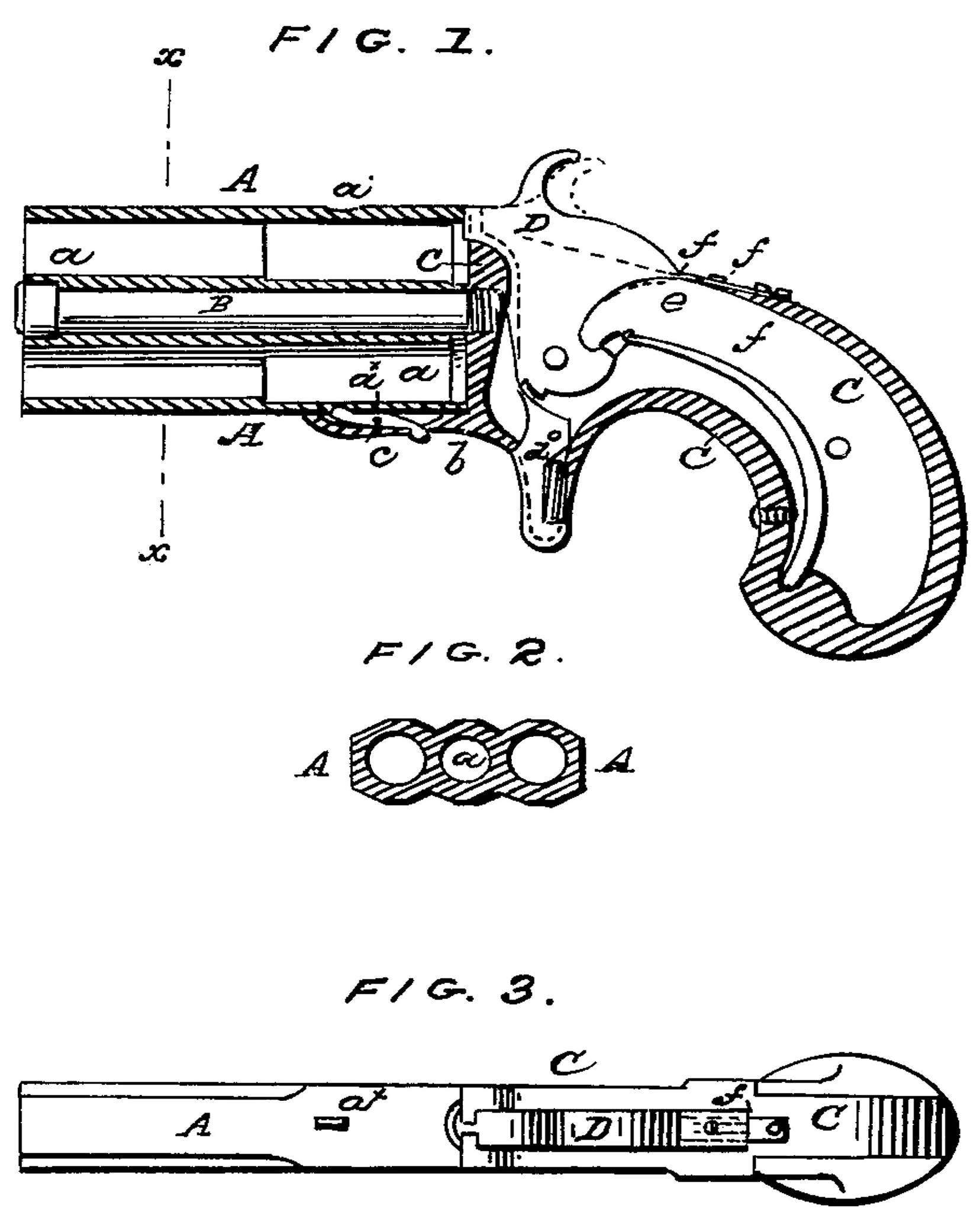
Figure 1 is a longitudinal section of a pistol made according to my invention.
Figure 2 is a transverse section of the same taken in the line x x of fig. 1.
Figure 3 is a plan view of the same.
Similar letters of reference indicate corresponding parts in all the figures.
This invention is more especially applicable to pistols, and relates to that class of fire-arms in which the barrels turn upon a longitudinal stem or spindle, connecting them with the frame of the arm; and
It consists in the construction, in a single piece, of two barrels, arranged upon opposite sides of an axial bore, through which the stem just mentioned is passed, in attaching the barrels to the frame, whereby the barrels may be manufactured or fitted up at a very moderate cost, and are also rendered very strong.
The invention further consists in a spring-catch, arranged in the frame of the pistol, and in such relation with the rotating barrels and the trigger that not only may the barrels be locked in position for firing, but may also, when required, be released from the catch by a very convenient movement of the finger which operates the trigger in firing.
The invention further consists in a slide, arranged upon the frame, and in relation with the notched rear portion of the hammer, in such manner that the latter may be locked fast, either while standing at half cock, or when down, with its face upon the base of the cartridge, thereby serving to effectually prevent an accidental discharge of the arm.
To enable others to understand the construction and operation of my invention, I will proceed to describe it with reference to the drawings.
The barrels A are formed of a single block or piece of metal, through which, between and parallel with the barrels, is a bore, a through which is passed the axial stem or spindle, B, connecting the barrels with the frame, C. By thus making the two barrels from a single or solid piece, or block, they are rendered very cheap in construction, and also very strong, while their arrangement upon opposite sides of the stem B insures the position required in a two-shooting pistol of the class or variety to which this belongs.
Formed in the outermost side of each barrel is a cavity or recess, a*, and provided in the lower end and forward portion b of the frame C is a pivoted catch, c, the forward end of which is pressed into the recess a* of the barrel which may be lowermost, by means of a suitable spring, a”, thus securely holding the barrels, to prevent them from turning upon their stem B, except when depressed, or brought away therefrom, as presently explained.
The rear extremity of the catch c projects downward, through a slot in the just hereinbefore-mentioned portion of the frame, in such contiguity with the trigger d of the arm, that the finger ordinarily employed to operate the trigger may be conveniently pressed upward, in such manner that the rear end of the catch will be forced upward, thus depressing the forward end thereof, to bring it from the recess a* in the lowermost barrel, whereupon the barrels may be turned with the fingers, to bring the lower barrel uppermost, so that the cartridge therein may be acted upon by the hammer, which is shown at D.
As one of the barrels is brought lowermost, its outer surface, being inclined as it touches the forward end of the spring-catch, forces such end downward until the barrel, being brought to its place, the end of the catch fits into the recess a* in the barrel, and holds the same in place.
It is preferred that a groove, semicircular in its cross-section, and of suitable size, be formed longitudinally in the forward portion of the right-hand side of the frame B, in such manner that, when the barrels are brought into a position at right angles to that just described, the cartridges may be conveniently passed into the open rear ends thereof, while the same are thus brought in line with the groove.
Working longitudinally in suitable guides, provided at the top of the frame C, and immediately in rear of the hammer, is a slide, f. The rearmost portion of the hammer constitutes a toe, e’, just above which is a notch, f’. When the hammer is completely down, as, for instance, when resting with its face upon the base of the cartridge, the slide f may be pushed forward, with its forward extremity under the toe e’ of the hammer, so that it will effectually prevent the latter from being brought back.
When preferred, previous to operating the slide, the hammer may be brought to half cock, as shown in red outline in fig. 1, whereupon, the slide, being moved forward, will catch in the notch f”, and thus prevent the hammer from being moved either forward or backward without first withdrawing the slide therefrom, so that, by this means, all liability of accidental discharge may be avoided.
What I claim as my invention, and desire to secure by Letters Patent, is–
1. The spring-catch c, arranged for operation by the trigger-finger, and in the frame C, and with reference to the two rotating barrels and the trigger, substantially as and for the purpose specified.
2. The slide f, arranged upon the upper side of the frame C, and in relation with the notched rear portion of the hammer D, substantially as and for the purpose specified.
F. WESSON.
Witnesses:
R. WESSON, Jr.,
A. H. MIRICK.