
US 385009
UNITED STATES PATENT OFFICE.
DAVID HALL RICE, OF BROOKLINE, MASSACHUSETTS, ASSIGNOR TO THE
MARLIN FIRE ARMS COMPANY, OF HARTFORD, CONNECTICUT.
EXTRACTING MECHANISM FOR REVOLVERS.
SPECIFICATION forming part of Letters Patent No. 385,009, dated June 26, 1888.
Application filed April 14, 1888. Serial No. 270,667. (No model.)
To all whom it may concern:
Be it known that I, DAVID HALL RICE, of Brookline, in the county of Norfolk and State of Massachusetts, have invented a certain new and useful Improvement in Revolving Fire Arms, of which the following is a specification.
My invention relates to revolving fire-arms; and it consists in certain new and useful constructions and combinations of the several parts of the same, substantially as hereinafter described and claimed.
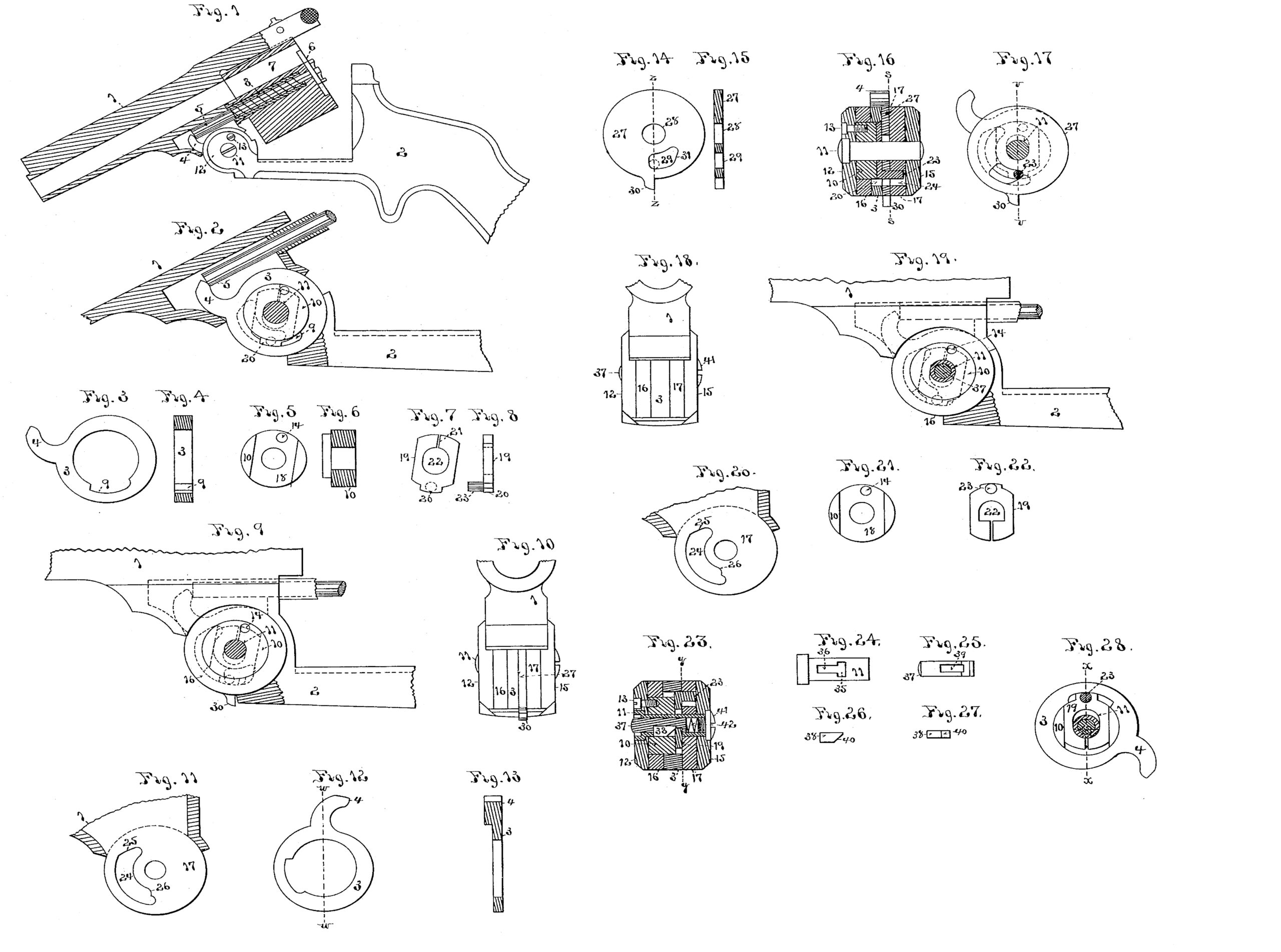
In the drawings, Figure 1 is a side view, partially in section, of a revolver constructed according to my invention. Fig. 2 is an enlarged view of a portion of the same, with part of the joint removed to show the internal construction. Figs. 3 and 4 are respectively side and sectional views Of the lifter. Figs. 5 and 6 are respectively side and sectional views of the hub which the lifter revolves around. Figs. 7 and 8 are respectively face and edge views of the slide which moves to and fro in the hub. Fig. 9 is the same as Fig. 2, except that only the outer leaf of the joint part of the frame is removed, and it is shown in a closed position, and an addition to the lifter mechanism is introduced. Fig. 10 is an end view of Fig. 9, showing the joint of the arm. Fig. 11 is a portion of the barrel part of the joint. Fig. 12 is a side view of the lifter in a modified form. Fig. 13 is an edge view of the same in section on line w w. Fig. 14 is a face view of the unlatching-disk. Fig.15 is an edge view of the same in section on line z z. Fig. 16 is a section through the joint of the arm in Fig. 10 on the dotted line v v of Fig. 17. Fig. 17 is a side view of the same, showing its position with relation to the joint of the arm and lifter in dotted lines, being a section through Fig. 16 on the line s s. Fig. 18 is an edge view of the joint shown in Figs. 1 and 2. Fig. 19 is the same as Fig. 9, with a modification of the unlatching device. Fig. 20 is the same as Fig. 11. Fig. 21 is a face view of the hub around which the lifter rotates. Fig. 22 is a face view of the slide which works in the same. Fig. 23 is a central section through the joint of Fig. 18 vertically. Fig. 24 is a side view of a modification of the form of pivot-pin for said joint. Fig. 25 is the plunger which works in the same. Fig. 26 is a side view of the cam piece fitted into said plunger, and Fig. 27 is an edge view of the same. Fig. 28 is a section through Fig. 23 on the line y y.
My improvements relate particularly to the extractor mechanisms of revolving fire-arms of the kind patented to C. A. King August 24, 1869, No. 94,003.
The barrel 1 of the arm is pivoted to the frame 2, so as to carry the lifter 3 in the joint. The finger 4 of the lifter bears against the end of the rod 5, to which the extractor 6 is attached at the other end. The cylinder 7 is supported upon the tubular pin 8, fixed in the barrel, and the extractor is retracted into the same, in the usual manner, by a spiral spring around its stem or rod 5. The construction and operation of these parts are well known, and will be readily understood without further description.
The extractor-lifter 3 is made in the form of a ring, Figs. 3 and 4, having the notch 9 on its inside edge. When in place in the joint of the arm, this ring 3 is mounted upon the hub 10, on which it is free to revolve, as hereinafter described. The hub 10 is a mere enlargement of the joint-pin 11 of the arm where it surrounds the same, and it is secured to the leaf 12 of the frame part of the joint by the screw 13, which enters the hole 14 in the hub, Figs. 1,5, and16. The frame carries the outside leaves, 12 and 15,of the joint,and the barrel the inside leaves, 16 and 17, of the usual construction, and the extractor-lifter revolves between the latter. In order to get the hub 10 into its place in the joint around the pin 11, the leaf 16 of the barrel part is bored out the size of the hub, while the opposite leaf is concentrically bored the size of the axial pin 11. The lifter 3 is then slipped edgewise into place between the barrel joint-leaves 16 and 17, and the hub 10 is passed sidewise through leaf 16 and the lifter. The leaves 12 and 15 of the frame part of the joint are now slipped into place outside of the barrel parts of it, and the axial pin 11 inserted in the usual way. The screw 13 is inserted through leaf 12 into hole 14 in the hub and the joint is complete. It will now be seen that the hub 10 always travels with the leaf 12 of the frame and axial pin 11 and forms an enlargement of the pin, around which leaf 16 of the barrel and the lifter revolves, while leaf 17 of the barrel revolves directly upon the pin 11. If this were all of the construction of the parts, the lifter would simply revolve around the hub 10 and have no means of actuating it to force out the extractor; but the alternating action of locking the lifter 3 to the hub 10 and releasing it after the extractor has ejected the cartridges is accomplished in the following manner:
Across the face of hub 10, which rests against the inner face of barrel joint-leaf 17, is cut a slot, 18, at right angles to the axis of the hub; In this slot is fitted a sliding latch, 19, made as long as the diameter of the hub 10. One end of this latch is formed into a square-edged nose, 20, capable of entering into the notch 9 of the lifter 3, and thus locking the lifter and hub 10 together. The latch 19 is a little wider at the other end than its groove 18 in hub 10, and has a slot, 21, cut through it to allow it to be sprung together and have a frictional bearing in the hub. The latch 19 also has the elongated hole 22 through it, to allow it to slide in the hub to and fro around the joint-pin 11, which passes through it. To properly move this latch in locking and unlocking the lifter 3 a pin part, 23, projects outward from its face into a curved slot, 24, in the barrel joint-leaf 17, Fig. 11. This curved slot is of a sufficient breadth radially to the joint axis to allow the pin part 23 to travel around in it whether the slide 19 be pushed out into the lifter 3 or drawn entirely back into the hub 10, and it has a cam-shaped bevel, 25, at one end of it, which, consing into contact with the pin 23, will push the latch 19 into the hub 10, and another carved slot, 26, at the other end, which, coming into contact with pin part 23, will push the latch out into the notch 9 in the lifter 3. The position of these parts is shown in dotted lines in Figs. 9 and 17.
The operation of the mechanism is as follows, the parts having been put together, as before described, with the latch 19 in its place in hub 10: When the arm is closed, as shown in Fig. 9, the cam-shoulder 26 of slot 24 in leaf 17 comes into contact with pin part 23. of latch 19 and pushes the nose 20 of the latch outward into notch 9 in the lifter 3. The lifter is now locked to the hub 10 and frame 2. When the parts are swung into the position shown in Figs. 1 and 2, the continued movement of opening the pistol will cause the finger 4 of the lifter to force out the extractor. When the barrel has been completely opened and the lifter has done its work, the cam-shoulder 25 strikes pin 23 and withdraws latch 19 into hub 10. This releases the lifter 3 from the hub and the extractor-spring causes the lifter to revolve backward around the hub to the position shown in Fig. 1 with relation to the barrel. The closing of the arm repeats the movements, as before described.
Figs. 10 to 17 show the additional feature of a cam added to the device, whereby the barrel of the pistol may be opened and swung down without extracting the cartridges in case it is desired to inspect them before discharging the pistol. In this construction a portion of the thickness of the annular part of the lifter is removed and the disk 27, of proper thickness to fill up this part cut away, is introduced between the lifter and barrel joint-leaf 17, the hub 10 being also shortened sufficiently to admit the disk. This disk 27 revolves on the joint-pin 11, which passes through its central hole, 28, and it has a spur, 30, on its periphery to turn it by with the finger. Through it, opposite to the slot 24 in the barrel hinge leaf 17, is cut a slot, 29, to allow the pin part 23 of the latch 19 to pass through the disk into the slot 24, as before described, and as shown in section in Fig. 16. On one side of the slot 29 it terminates in a cam-shaped bevel, 31, so proportioned that when the disk 27 is revolved and this bevel is brought against the pin part 23 of latch 19, as shown in Figs. 14 and 17, the latch will be pushed into the hub 10 and the lifter unlocked therefrom.
When it is desired to open the barrel without extracting the cartridges, the barrel is to be opened as far as shown in Fig. 1 and the disk 27 turned by the spur 30 from the position of Fig. 14 to that of Fig. 17, which withdraws the latch 19 into hub 10, and the arm may continue to be opened without operating the extractor-lifter.
In case the disk 27 is not moved the operation of the lifter and its release will be effected precisely as before, as the disk can never operate to unlock the lifter automatically. The disk 27 might be made to revolve around the hub10 and have bevels or spurs to operate on the end of latch 19, if desired, instead of against the pin part of it.
Figs. 18 to 28, inclusive, show another form of unlocking device for the extractor-lifter. In this construction all the parts are similar to those first described, except the pivot-pin 11 and the hole 22 through slide 19, the latter being made square at one end instead of oval. The pivot-pin is made tubular with its head countersunk. Through its wall, across one side, is cut the slot 35 transversely. From this the longitudinal slot 36 is cut through its wall toward its head. The slot 35 is opposite the slide 19 in the joint and allows the square end of hole 22 in the latter to enter it, as shown in Fig. 23. The plunger 37 is introduced into the pivot-pin 11, as shown, and the steel cam-piece 38 is slipped into the mortise 39 in the plunger, thus securing the latter into the pivot-pin 11. The pivot- pin being inserted through the hub 10, the cam-piece cannot escape. The screw 41 is then screwed into the open point end of the pivot-pin 11, with the spiral spring 42 between it and the plunger 37, thus securing the parts together. When it is desired to draw back the latch 19 into hub 10, the outer end of plunger 37 is pressed upon by the finger and the bevel 40 of the cam-piece 38 forced against the square side of the hole 22 in the latch 19, thus unlocking the lifter from the hub 10 and preventing its acting upon the extractor. It will be observed that in this construction of the latch for locking the lifter to the frame part 2 of the arm the latch is operated in both directions by cam-shoulders on the barrel part of the arm, while it is Mounted in and carried by the frame part 2 thereof, the hub 10, in which it works, being but an attachment to the latter. By my change in the location of the latch 19 and operating it positively in both directions by the cam-shoulders 25 and 26 of the barrel part of the arm I am not only able to dispense with any spring to operate it, but I inclose it entirely within the lifter and leave no joint exposed to being fouled up by dirt or gases of powder around it, and the construction is neater and better than when the latch is exposed at either one or both ends during its operation.
What I claim as new and of my invention is—
1. The combination of the barrel part 1, provided with the cam-shoulders 25 26 and a joint part, the frame part 2; having the attached pivot on which the barrel joint part is hung, the latch 19, mounted in said pivot and adapted to engage with said cam-shoulders, arranged to act thereon in opposite directions and be moved in and out thereby, the annular lifter arranged to revolve on said pivot and provided with the notch 9 for engagement with said latch, and the extractor actuated by said lifter, substantially as described.
2. The combination of the barrel part 1, having its joint part and provided with the cam-shoulders 25 26, the frame part 2, pivoted thereto, the sliding latch 19, mounted in said frame part and adapted to be moved positively both in and out of the same by said cam-shoulders, arranged to act in opposite directions thereon in the opening and closing of the barrel, the lifter pivoted on the joint-pin and provided with the notch 9 for engagement with said sliding latch, and the extractor actuated by said lifter, substantially as described.
3. The combination of the barrel 1, having a hinge part and cam-shoulders 25 26, the frame 2, having a pivot part, 10, around which the barrel turns, the latch 19, arranged to move in and out through a slot in said pivot part by engagement with said cam-shoulders, arranged to act in opposite directions thereon, the lifter surrounding said pivot part 10 and slide 19, and having the internal notch, 9, to receive the nose of said slide, and the extractor actuated by said lifter, substantially as described.
4. The combination of the barrel 1, having the joint-leaf 16, provided with an axial nose adapted to receive the hub 10, and having the joint-leaf 17, provided with cam shoulders 25 26, the frame 2, provided with the attached hub 10,around which the joint-leaf 16 revolves, the latch in said hub arranged to be moved in and out of the same by engagement with said cam-shoulders, arranged to act in opposite directions thereon, the annular lifter provided with the internal notch, 9, and arranged to revolve around said hub between the barrel joint-leaves 16 and 17, and the extractor actuated by said lifter, substantially as described.
5. The combination of the barrel 1, provided with a joint part, the frame 2, provided with an axis upon which said joint part revolves, the latch 19, located in said axis and arranged to be moved in and out of the same by contact with shoulders on the frame, the lifter 3, surrounding and inclosing the said latch within it, and having the internal notch, 9, to receive the same, the extractor actuated by said lifter, and an independent.movable cam-surface connected with said joint of the frame and barrel, and arranged to be moved against said latch by hand and withdraw it into said axis at will, substantially as described.
6. The combination of the barrel 1, provided with joint-leaves 16 and 17, the latter being provided with the slot 24, and cam-shoulders 25 26 at opposite sides of said slot, the frame 2, provided with the axis on which the barrel part turns, the lifter 3, surrounding and turning upon and with said axis and provided with the notch 9, the extractor actuated by said lifter, and the latch mounted in said axis and arranged to move radially inward and outward therein, and having a projecting pin part, 23, reaching into said slot 24, made narrower than the breadth of said slot radially, whereby it is enabled to travel through the outer portion of the slot in one direction and the inner portion of it in the other direction when moved by said cam shoulders, substantially as described.
7. The combination of the barrel 1, having the joint-leaves 16 17, the frame 2, having the joint-leaves 12 15 and the axis connecting these joint leaves together, the annular lifter having the notch 9 on its internal edge, a latch mounted in the frame part and arranged to be engaged with and released from said internal notch by contact with shoulders on the barrel arranged to act in opposite directions thereon, and the extractor actuated by said lifter, substantially as described.
8. The combination of the barrel 1, having the joint-leaves 16 17, the frame 2, having the attached axis on which these leaves revolve, the latch 19, mounted in said axis and arranged to move in and out of the same by contact with shoulders on the barrel, the lifter mounted on said axis and provided with the internal notch, 9, to receive the latch, the extractor actuated by said lifter, and the revolving disk 27, provided with the cam-shoulder 31, adapted to be brought against said latch by revolving the disk, substantially as described.
9. The combination of the annular lifter 3, provided with the notch 9, its central pivot, 10, attached to the frame, provided with the latch 19, adapted to engage with said notch, the shoulders 25 26 upon the barrel, arranged to engage with said latch and act in opposite directions thereon and move it into or out of such engagement, and the extractor actuated by said lifter, substantially as described.
10. The combination of the annular lifter provided with the notch 9, its central pivot, 10, attached to the frame, provided with the latch 19, adapted to engage with said notch, the Cam-shoulder 25 upon the barrel, arranged to engage with said latch and move it out of engagement with the lifter, and the extractor 10 actuated by said lifter, substantially as described.
DAVID HALL RICE.
Witnesses:
WILLIAM P. BLAKE,
N. P. OCKINGTON.