
US 383701
UNITED STATES PATENT OFFICE.
HOMER M. CALDWELL, OF WORCESTER, MASSACHUSETTS, ASSIGNOR TO THIS
WARRINGTON & RICHARDSON ARMS COMPANY, OF SAME PLACE.
REVOLVING FIRE-ARM.
SPECIFICATION forming part of Letters Patent No. 383,701, dated May 29, 1888.
Application filed March 7, 1888. Serial No. 966,451. (No model.)
T0 all whom it may concern:
Be it known that I, HOMER M. CALDWELL, a citizen of the United States, residing at Worcester, in the county of Worcester and State of Massachusetts, have invented certain new and useful Improvements in Fire-Arms, of which the following, together with the accompanying drawings, is a specification sufficiently full, clear, and exact to enable persons skilled in the art to which this invention appertains to make and use the same.
This invention relates to improvements in mechanism for operating shell-extractors in that class of fire-arms wherein the extractor is fitted in the rear end of the charge-cylinder and supported on the end of a center stem that is worked for ejecting the shells from the cylinder when tilting forward the barrel, by means of a finger-disk in connection with the hinging-joint, the object of my present invention being to provide an extractor-actuating mechanism that will operate with efficiency, and which can be manufactured with practical facility and economy; also, to afford means whereby the extractor can be released or thrown down from any position of its movement when desired. These objects I attain by the mechanism shown and described, the particular subject-matter claimed being hereinafter definitely specified.
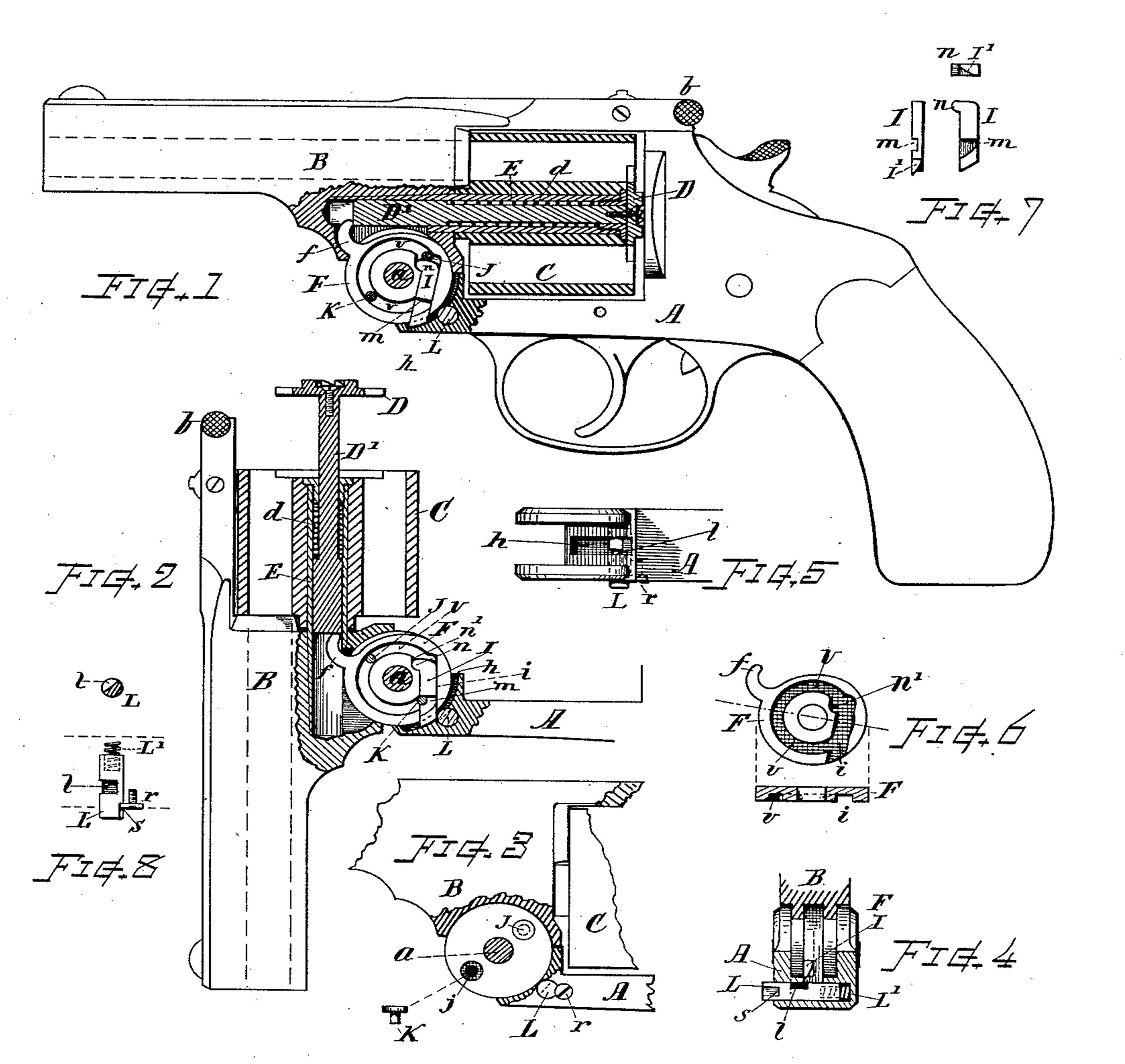
In the drawings, Figure 1 is a part side, part vertical, sectional view of a revolver, showing my improved extractor mechanism in normal position. Fig. 2 is a similar view showing the barrel tilted forward to a position immediately preceding that at which the finger-disk stop is released. Fig. 3 shows the arrangement of
the stop-actuating pins in the side of the barrel-hinge; also the position of the intercepting stud and screw for confining it in the frame. Fig. 4 is a transverse sectional view showing the back of the hinge-joint and intercepting stud. Fig. 5 is a top view of the fore-end of the frame with the barrel-hinge removed. Fig. 6 shows the detail of the finger-disk. Fig. 7 shows the detail of the stop-bolt, and Fig. 8 shows the detail of the intercepting-stud.
In referring to parts, A denotes the frame; B, the barrel hinged to the fore end of said frame to swing on the pivot a, and locked to the upper part of the frame by the latch d, when in normal position. C indicates the cylinder; D, the extractor-plate, having its stem D’ fitted within the cylinder-supporting quill E, and provided with a spring, d, all of which parts may be constructed and arranged in the usual well-known manner.
F indicates the extractor-operating gear or disk mounted between the two ears or sides of the barrel-hinge on the pivot a, and provided with the finger f, that engages the extractor-stem, in the manner illustrated, for raising the extractor in the usual manner.
I indicates a longitudinally-movable stop-bolt fitted within a groove, i, formed in one side of the disk F and arranged so that its end can project from the periphery of the disk or be retracted, so as to be flush with the periphery thereof. Said bolt is provided with a projecting lug, n, at its inner end, while the disk is fitted with a recess, n’, to receive said lug n, thereby retaining the bolt within its groove and confining it to a given limit of movement. A recess and shoulder, m, is formed on one side of the bolt, and its outer end is provided with a lateral bevel or incline, I’, on its projecting portion, as shown in Fig. 7.
The barrel-hinge is provided in one side with counterbored openings j, in which are arranged short pins or studs J and K, (see Fig. 3,) the heads of which are confined within the counterbore of the openings j, flush with the cheek of the hinge, while the points of said studs extend through the side and project into curved grooves or an annular recess, v, formed in the side of the disk F in positions to engage the stop-bolt I, the pin J working against the head of said bolt and the pin K working against the shoulder m, as hereinafter explained.
The fore-end of the frame A is fitted with a recess, h, within which the projecting end of the stop-bolt I works, and transversely across said recess there is arranged adjacent to the periphery of the hinge and disk a stud, L, for intercepting the stop-bolt and thereby preventing backward movement of the finger-disk as the barrel is tilted forward. Said stud is formed with a notch, l, in its side, which notch l is of sufficient width to permit the passage of the end of the stop-bolt I when said notch is in line with the recess h. The normal position of the stud L is, with its notch l, disposed so as to be out of line, or nearly so, with the recess h, and a suitable spring, L’, is provided for forcing the stud outward, so that its body will intercept the stop-bolt when normally disposed. The intercepting-stud can be readily moved to bring the notch into line with the stop-bolt by pressure of the thumb on its outer end sufficient to overcome the pressure of the spring L’, and the retractor mechanism is thus released. Upon removing the thumb the stud will be again pressed outward by its spring L’. The stud L is retained in the frame by means of a small screw, r, the head of which engages a shoulder, s, formed on the side of the stud, as indicated. The intercepting-stud L is located at a short distance back from the position which the end of the stop-bolt occupies when the barrel is in normal position, (see Fig. 1,) thus allowing slight tilting movement before the stop-bolt is intercepted and affording an interval sufficient to permit of the cylinder and shells being raised from the recoil-plate before the extractor action for ejecting the shells from the cylinder commences.
The operation of my improved mechanism is as follows: When the barrel is in normal position, (see Fig. 1,) the pin J rests against the head of the stop-bolt I and causes said bolt to protrude from the periphery of the disk F. When the barrel is unlatched and tilted forward, the finger-disk F, by reason of the force of the extractor-spring d, is caused to swing with the barrel-hinge until the projecting end
of the stop-bolt I is intercepted by the stud L, and further rotative movement of the disk is for the time prevented thereby, while the further tilting of the barrel causes the pin J to move away from the head of the stop-bolt, while the finger-disk remains stationary with the frame, causing the extractor D to be raised from the rear end of the cylinder by the action of the finger f in the usual manner. When the barrel has reached a position substantially as indicated in Fig. 2, the pin K is brought into contact with the shoulder m on the stop-bolt I, and said stop-bolt is thereby drawn into the disk, thus releasing its outer end from the intercepting-stud L, and the disk being then free to rotate, the extractor is immediately thrown down by the action of its spring d, the disk swinging on the pivot-pin a and carrying the stop-bolt around with it until its head strikes against the pin J, which forces the bolt outward to its first position. When the barrel is swung back to normal position, the beveled end of the stop-bolt passes into the slot l in the intercepting-stud; and, by reason of its beveled form, overcomes the pressure of the spring L’ and moves said stud inward sufficient to allow the end of the stop-bolt to pass through said notch l to its original forward position.
If it is desired to throw down the extractor at any intermediate position of the tilting action, it can be done by pressing in the intercepting-stud L, so as to bring the notch l in line with the groove h. This will release the stop-bolt and allow it to pass through the notch, and the extractor will drop by the action of the extractor-spring d. The barrel and cylinder can be tilted without operating the extractor by simply pressing in the stud L before tilting it.
It will be noticed that the end of the stop-bolt I, working within the groove h, and the interceptor-stud L are inclosed within the frame, and are thus securely protected from any accidental derangement which might otherwise occur by contact with any object were such parts outside or exposed.
The head of the intercepting-stud L is herein shown, for clearness of illustration, as projecting slightly from the frame; but in practice it may be desirable to make the head of said stud flush with the side of the frame and form a slight depression or recess in the frame about the stud to facilitate pressing the end thereof.
The mechanism constructed as herein described can be readily and economically manufactured. The parts are simple, easily made, and are not liable to derangement when in use, thus producing an improvement that is very desirable and convenient for operation.
I am aware that it is a customary practice to operate shell-extractors having a central stem by means of a disk arranged in the hinging-joint and provided with a finger that engages with the extractor-stem, and that various devices have been employed for locking and releasing said finger-disk at positions for effecting action of the extractor. It will therefore be understood that do not herein claim, broadly, an extractor operated by a finger disk located at the hinging-joint; but my invention refers to and comprises the mechanism of improved construction herein illustrated and described.
What I claim as of my invention, and desire to secure by Letters Patent, is—
In an extractor mechanism for fire-arms, the combination, with the barrel-hinge ear, the finger-disk mounted to swing on the hinge-pivot between said ears, and the finger-disk stop-bolt supported in said finger-disk to be retracted or projected beyond the periphery thereof, of two studs supported in the side of said barrel-hinge ear with their ends extending into the recessed side of said finger-disk at positions to respectively engage and operate said stop-bolt, one when the barrel is tilted forward and the other when the barrel is swung back to normal position, substantially as set forth.
2. In an extractor mechanism for fire-arms, the finger-disk having the groove i, with a recess, n’, in the side thereof, in combination with the longitudinally movable stop-bolt I, fitted to slide free within said finger-disk groove, and having a lug, n, projecting from its side into said recess n’, together with studs borne by the hinge-ear and entering the groove to operate said stop-bolt, substantially as and for the purpose set forth.
3. The combination, with the frame and barrel-hinge, shell-extractor, and extractor-spring, in a fire-arm, of the grooved finger-disk, the stop-bolt having a notch or shoulder, m, fitted within said finger-disk with one of its ends projectable from the periphery thereof, two studs carried by the barrel-hinge, which engage and move said stop-bolt, and an intercepting-stud supported in the frame adjacent to the periphery of the disk,against which said stop-bolt is arrested for effecting lifting action of the extractor, substantially as set forth.
4. The combination, substantially as described, with the frame and barrel-hinge, shell extractor stem, and extractor-spring, in a firearm, of the finger-disk F, the stop-bolt I, fitted in said finger-disk and having a shoulder, m, and laterally-beveled outer end, two studs, J and K, fixed in the barrel-hinge, and the spring-actuated intercepting-stud L, having the notch 2 and supported in the frame A adjacent to the periphery of said finger-disk for engaging the end of the stop-bolt, for the purposes set forth.
5. In a fire-arm of the class described, the fore end of the frame provided with the recess or groove h, in combination with the barrel-hinge, extractor-finger disk carrying a stop-bolt the end of which works in said groove, and the laterally-movable spring-pressed intercepting stud arranged across said groove, substantially as set forth, whereby the stop-bolt is protected by inclosure within the frame.
6. In an extractor-operating mechanism for fire-arms, the combination, with the finger-disk F and stop-bolt I, beveled on its outer end, of the spring-pressed intercepting-stud L, supported in the frame for engaging said stop-bolt, and having the notch l, the spring L’ at the end of said stud, and the stud-retaining screw r, for the purposes set forth.
Witness my hand this 2d day of March, A. D. 1888.
HOMER M. CALDWELL.
Witnesses:
CHAS. H. BURLEIGH,
WM. A. RICHARDSON.