
US 380361
UNITED STATES PATENT OFFICE.
WILLIAM H. SPRAGUE, OF JAMESTOWN, NEW YORK.
REVOLVER.
SPECIFICATION forming part of Letters Patent No, 380,361, dated April 3, 1888.
Application filed March 3, 1886. Serial No. 193,888. (No model.)
To all whom it may concern:
Be it known that I, WILLIAM H. SPRAGUE, a citizen of the United States, residing at Jamestown, in the county of Chautauqua and State of New York nave invented certain new and useful Improvements in Fire-Arms, of which the following is a specification, reference being had therein to the accompanying drawings.
My invention relates to improvements in fire-arms which are loaded from the breech, either in revolving cylinders or other loading devices; and the object of my invention is to allow the cylinder or other loading device to occupy a position in the breech or handle with its axis at an angle to the line along which the projectile is delivered from the muzzle, and thereby rendering the complete fire-arm more compact, lessening the weight of pocket-arms, and making them more convenient in use and transportation. I attain these objects by the mechanism illustrated in the accompanying drawings, in which—
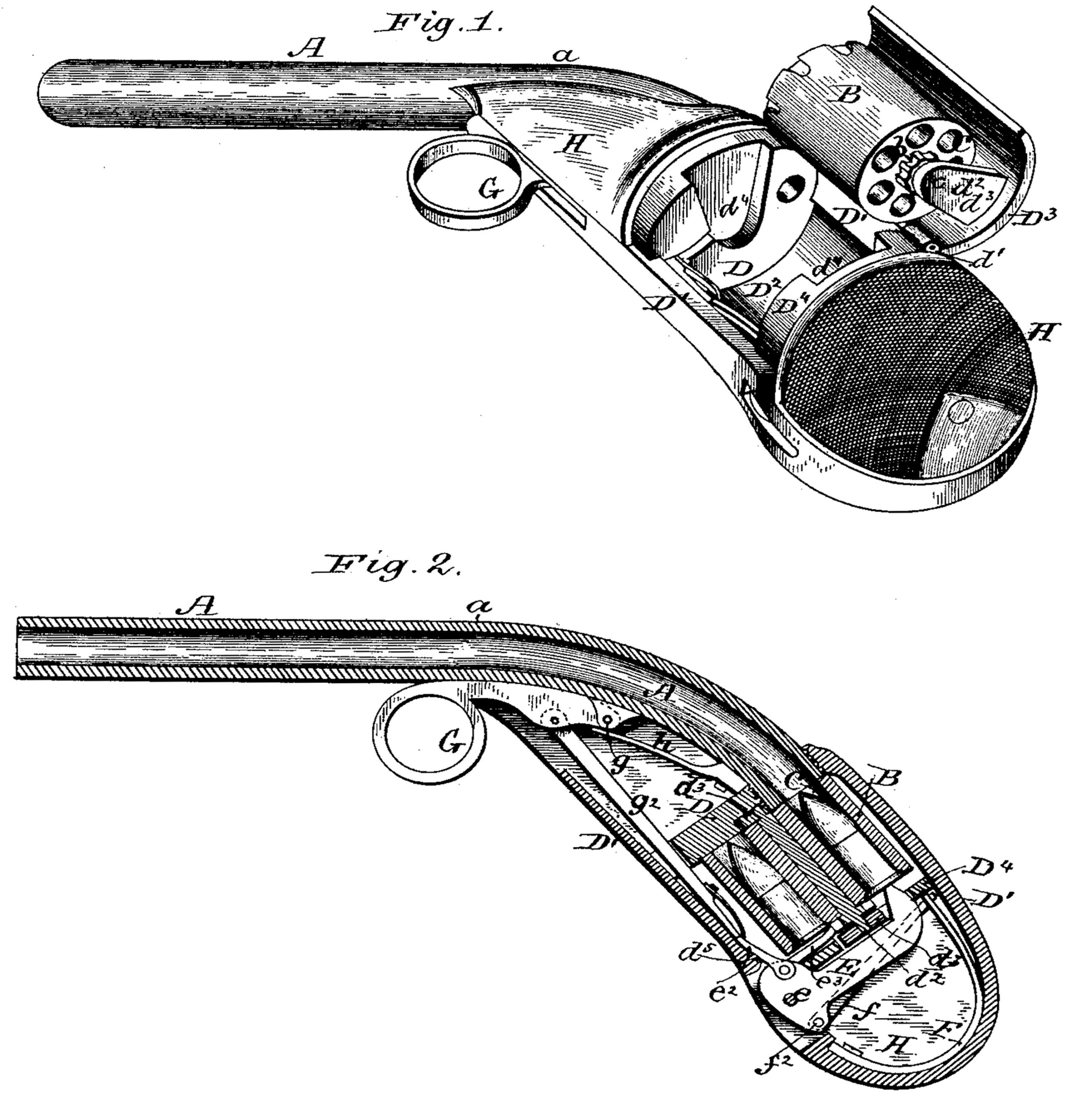
Figure 1 is a perspective view of a pocket revolver constructed in accordance with my invention, and showing the breech open. Fig. 2 is a longitudinal vertical section of the same.
The barrel A is curved for a part of its length at the breech end in the general direction of the handle or breech of the arm, to allow the cylinder B or other loading device to be placed within the handle of the pistol, or in a gun within the breech of the stock, so as to render the arm compact and its surface free from abrupt projections.
The barrel A may be constructed in two sections joined at the point a, or in one section with the part in the rear of the point a properly curved. The orifice of the loading device C, or of one of the chambers of the cylinder B, containing the charges, is in proper alignment with the rear end of the barrel A and in contact therewith, and it is obvious that upon the discharge of the arm the projectile will follow the curved section of the barrel to the point a, and from thence will be delivered in a straight line to and out from the muzzle. The rear end of the barrel is screwed or otherwise secured to the forward transverse partition, D, of the frame. This frame may be of any suitable form, according to the nature of the fire-arm. In the present instance it has a central longitudinal rib, D’, that forms the stock of the pistol. The top and bottom portions of this rib are united on one side by a semicircular shell, D2, that forms one-half of the walls inclosing the cylinder B, and the semicircular shell D3 on the opposite side is hinged at d’ to the upper part of the rib D’. This hinged shell has two internal lugs, d3, having a perforation in their free end, through which passes the axial pin d2 of the cylinder B. The front and rear transverse partitions, D D4, have recesses d4, to receive the lugs d3, so that the front face of the cylinder B will fit against the partition D and the rear of the barrel and prevent the escape of gases at that point.
The hinged shell d2 may be retained closed simply by the hand of the user while grasping the stock or breech of the pistol, or by any suitable spring-catch. This pistol is provided with a suitable hammer, E, pivoted to the frame at its lower end at e.
To force its striking upper end forward, the hammer is connected by means of a link, f, with the bent spring F, the upper end of said link resting upon the free end of the spring, while the lower end of the link is pivoted at f2 to the rear end of the hammer. The trigger G may be either straight or provided with a ring at its outer end. It has its inner end pivoted to the frame at g, and a flat spring, h, bears upon it at that point. To the trigger is pivoted one end of the rod g2, and the opposite end abuts against one end of the arm e2, pivoted to the front of the hammer. This arm rests upon a projection, d5, of the frame, so that when the trigger is pulled and the arm e2 is pushed back its free end becomes sufficiently elevated to escape from in front of the rod g2 and permit the point of the hammer to strike forward under the impulse of its spring E. To the lower end of the hammer is also pivoted one end of a pawl, e3, the upper end of which is hooked and adapted to engage with the teeth of the ratchet-wheel b upon the rear of the cylinder B.
Upon the sides of the central rib or frame, D’, cheek-pieces H, of wood or other suitable material, are secured to inclose the moving parts of the mechanism.
Although I prefer as a load-receiver a cylinder with many chambers, said receiver may be made with a single chamber and be either movable or secured to the rear end of the curved barrel.
Having now described my invention, I claim—
1. In a fire-arm, a cylinder or load receiver located within the handle or breech of said arm, and having its axis at an angle to the line of delivery of the projectile from the muzzle, and hinged to the frame at the breech of the barrel, in combination with a barrel having a curved and a straight section, substantially as and for the purpose described.
2. In a fire-arm, the combination of a barrel having a downward curve at its breech, with its supporting-frame, a semicircular shell hinged to said frame at the breech of the barrel, and a cylinder or load-receiver secured to said shell ard moved therewith so as to bring a shell-holding chamber in alignment with the said barrel, substantially as and for the purpose described.
3. The combination of a pistol-barrel having a downward curve at its breech, its supporting-frame, and a shell hinged to said frame at the rear of the barrel, with a load-receiver located within the handle of said pistol and borne by the hinged shell, substantially as and for the purpose described.
In testimony whereof I affix my signature in presence of two witnesses.
WILLIAM H. SPRAGUE.
Witnesses:
JAMES I. FOWLER,
H. M. GAGE.