
US 376922
UNITED STATES PATENT OFFICE.
JOHN T. SMITH, OF ROCKFALL, CONNECTICUT.
REVOLVER.
SPECIFICATION forming part of Letters Patent No. 376,922, dated January 24, 1888.
Application filed Jane 6, 1887. Serial No. 240,400. (No model.)
To all whom it may concern:
Be it known that I, JOHN T. SMITH, of Rock-fall, in the county of Middlesex and State of Connecticut, have invented a new Improvement in Revolvers; and I do hereby declare the following, when taken in connection with accompanying three sheets of drawings and the letters of reference marked thereon, to be a full, clear, and exact description of the same, and which said drawings constitute part of this specification, and represent, in—
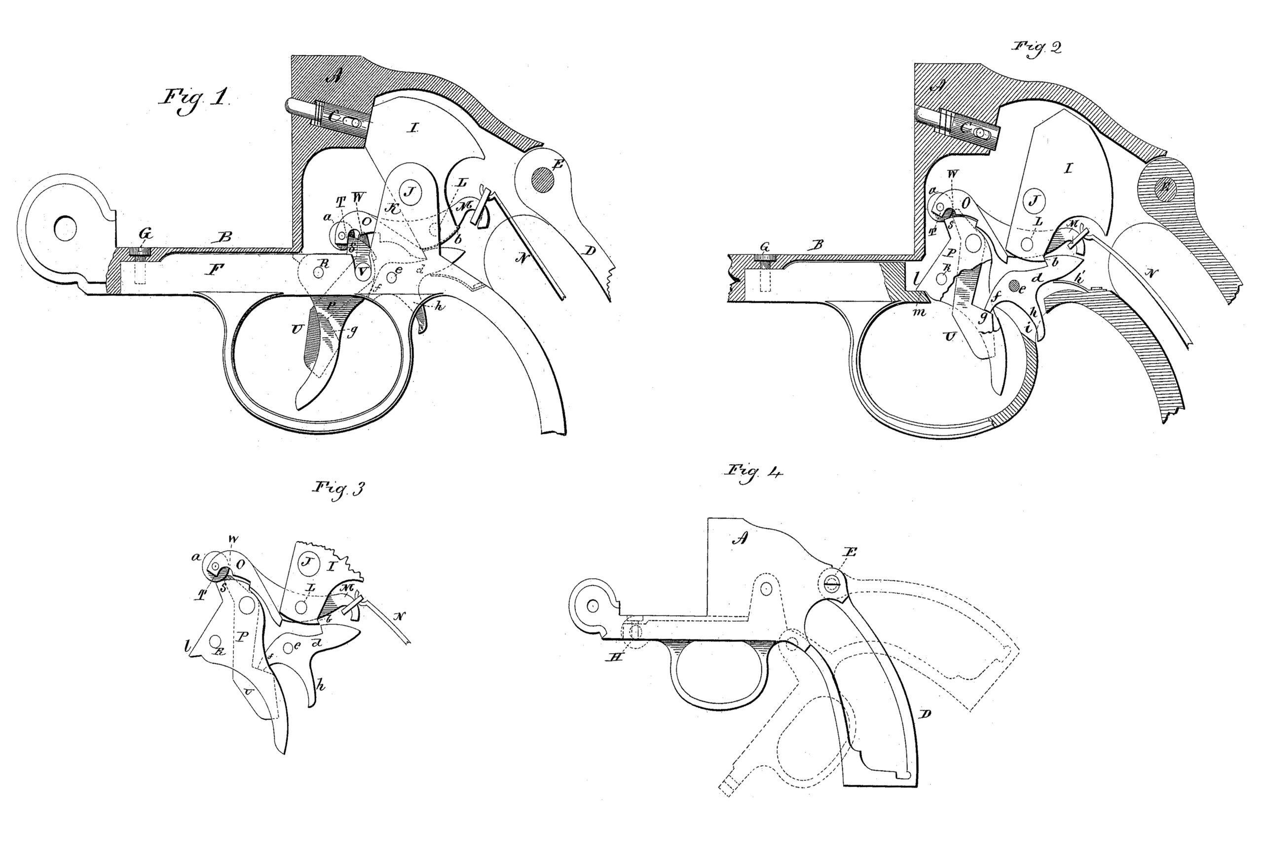
Figure 1, a sectional side view of the revolver, showing the parts in the normal or closed position; Fig. 2, the same view showing the parts in the position of the hammer cocked; Fig. 3, a detached view of the trigger and hammer connecting mechanism in the position of releasing the hammer; Fig. 4, a detached view of the frame, illustrating the method of hinging the two parts together.
This invention relates to an improvement in that class of revolvers in which the hammer is concealed entirely within the frame, no portion of it being exposed, and such as are commonly called “concealed hammers,” the object of the invention being to adapt the hammer to be set at full-cock and discharged at pleasure, or for firing without fall-cock engagement, and also to permit the hammer, after it has been set at full-cock, to be dropped easily, and without imparting a blow, whereby accidents arising from a hammer held at fullcock are avoided, and has also for its object to arrange the lock mechanism in one part of the frame, the said one part of the frame hinged to that portion which carries the recoil, and so as to be turned therefrom and expose the entire lock mechanism for examination or repairs.
In illustrating the invention I omit that portion of the frame which carries the barrel and the cylinder, such portions being unnecessary to the clear understanding of the invention.
A represents the recoil portion of the frame, from which an arm, B, extends forward, and to which the usual cylinder and barrel portion of the frame is hinged in the usual manner. In the recoil part of the frame A the firing-pin C is introduced in the usual manner, and so as to automatically fall back after it shall have been struck with the hammer.
D represents the handle portion of the frame, which is hinged at the upper side to the recoil portion upon a pintle, E. From its forward end an arm, F, extends into a recess upon the under side of the arm B, where it may be secured by a screw, G, introduced through the arm B into the arm F, (see Fig. 4,) and so that the handle portion of the frame D may be turned downward and away from the recoil or forward portion, A, as indicated in broken lines, Fig. 4. The recoil portion is hollow or recessed for the lock mechanism, in the usual manner; but the mechanism of the lock is secured entirely to the handle or hinged portion D, so that as the handle portion is turned downward from the recoil portion of the frame, as seen in broken lines, Fig. 4, the lock mechanism will be conveniently exposed.
While I prefer to hinge the handle portion D upon its upper side, as at E, it may be hinged forward, as indicated at H, broken lines, Fig. 4, and so as to turn downward and forward in opening, it being secured to the recoil portion, say, at the same point as the pintle E, that pintle in such case being a screw, which may be removed to detach the parts for the purpose of opening.
I represents the hammer, which is hung upon a pivot, J, in an upward projection, K, from the handle portion of the frame. (See Fig. 1)
In the hammer below the pivot J, I hang a lever or dog upon a pivot, L. One arm, M, of the lever extends to the rear of the pivot, to which the mainspring N is hung, in substantially the same manner as in my Patent No. 346,327. The other arm, O, of the lever extends forward of the pivot, and is utilized as a dog for cocking the hammer, substantially as in my patent before referred to.
In the frame below the forward end of the dog O the trigger P is hung upon a pivot, R, the trigger extending down into the guard in the usual manner. Above or in rear of the pivot the trigger is provided with a shoulder, S, which is adapted to engage the nose T of the dog when the hammer is in the down position, as seen in Fig. 1, and so that by pulling upon the trigger the shoulder S will engage the nose T of the dog, and, drawing it forward, will correspondingly draw the hammer toward the position of full-cock. In the principal trigger P an auxiliary trigger, U, is hung upon a pivot, V, and so as to work within the principal trigger. The upper end, W, of the trigger U extends above the upper end or shoulder, S, of the principal trigger, and is adapted to bear upon an anti-friction roll or corresponding surface, a, in the nose of the dog O.
When the parts are in the normal position, as seen In Fig. 1, if the principal trigger he pulled it will draw the dog forward and correspondingly turn the hammer rearward, as seen in Fig. 2, and as the trigger approaches its extreme forward position the nose W of the auxiliary trigger U will rest against the anti-friction roll a. The mainspring acts through the deg to hold the nose end downward and correspondingly hold the nose W of the auxiliary trigger rearward, which causes the lower end of the auxiliary trigger to project forward beyond the front face of the principal trigger, this projection being somewhat above the lower end of the principal trigger, as seen in Fig. 2. The auxiliary trigger rests against the forward edge of its recess in the principal trigger, so that in the pull of the principal trigger, as it approaches its extreme rear position, the nose W of the auxiliary trigger will bear against the roll a, and it will thus bear after the shoulder S of the principal trigger has escaped from the nose T of the dog O, so that the nose W of the auxiliary trigger serves to produce the last portion of the forward movement of the dog O, which brings the hammer to the full-cocked position, as seen in Fig. 2, where it is engaged by the shoulder b of the sear d, which is hung upon a pivot, e, in rear of the principal trigger.
From the sear forward of its pivot is a projecting finger, f, which stands in the path of a corresponding shoulder, g, on the auxiliary trigger. The sear is provided with a spring, h’, which forces it into engagement with the corresponding shoulder on the hammer when at full-cock, as seen in Fig. 2. If now the auxiliary trigger be pulled, its nose end will first act upon the dog to slightly raise its forward end, as indicated in Fig. 3, so as to raise the dog, that it may escape over the trigger. Then the shoulder g on the auxiliary trigger engages the finger f of the sear and turns the sear, so as to permit the hammer to escape and be thrown forward under the action of the mainspring, when the hammer and the dog will be thrown to the extreme rear position, the dog passing over the trigger. It will be understood that in thus cocking the hammer the pull is applied to the principal trigger, and for this purpose the principal trigger is extended below the auxiliary trigger, as before mentioned. Hence in making the pull upon the trigger the finger will be applied first below the auxiliary trigger to bring the hammer to full-cock, then upon the auxiliary trigger to produce the discharge. If, however, discharge is desired upon the pull of the trigger and without engagement of the sear, as for rapid firing, the finger is placed upon the auxiliary trigger, so as to press it backward into position to strike the sear, and then, as the hammer is brought to the position of full-cock, the auxiliary trigger will have pressed the sear out of the engaging position, as seen in Fig. 3, so that the hammer will not be caught, but, on the contrary, will escape so soon as the full-cock position is reached, the final disengagement being produced by the nose of the auxiliary trigger acting against the forward end of the dog to raise it so far as to permit its escape over the trigger, as seen in Fig. 3.
In the case of a concealed hammer without some indicator there is an uncertainty as to whether or not the hammer is cocked, and, if cocked, under ordinary constructions of the revolver it is extremely difficult to drop the hammer without imparting its blow. To permit such dropping of the hammer I construct the sear with a downward and rearwardly projecting finger, h, which extends through an opening, i, in the frame or guard below, and so that when the hammer is cocked, if one finger be placed upon the trigger and, say, the thumb upon the finger h of the sear, the trigger held near its rear position, the hammer will be released by the sear; but the dog will catch upon the trigger and be held by the finger, and so that under the pull of the finger, if the trigger be permitted slowly to move forward, the dog will be engaged with the shoulder S of the trigger and correspondingly permit the hammer to move slowly forward to its down or normal position, as seen in Fig. 1. Thus the hammer may be dropped or closed by a movement similar to that which is permissible in an exposed hammer, where the thumb is placed upon the hammer and the finger upon the trigger.
To surely arrest the trigger when the hammer is brought to full-cock, I construct it with a shoulder, l, say, forward of its pivot, and adapted to engage a corresponding shoulder, m, in the frame, as seen in Fig. 2. This position will be reached upon bringing the hammer to a full-cocked position and before it is possible for the auxiliary trigger to strike the sear, unless the finger shall have also borne upon the auxiliary trigger. By this provision the hammer may surely be brought to full-cock without danger of disengagement, and may be so held for the convenience of the person using the revolver.
The lock mechanism arranged in the handle portion of the frame, and thereby easily separable from the barrel portion, permits ready access to the lock, as occasion may require, for examination or repair. This feature of the revolver is applicable to revolvers having other lock mechanism than that which I have shown and described, and with equal advantage.
The downward or outwardly projecting finger h from the sear may be employed to advantage in revolvers having other mechanism between the principal trigger and the hammer than that which I have described such, for illustration, as the principal trigger with the auxiliary trigger omitted, the principal trigger itself being adapted to directly engage the sear—a, construction too well known to require particular description.
I claim—
1. In a revolver, the frame made in two parts, the division being between the handle portion and recoil portion of the frame, the handle portion of the frame hinged to the recoil portion at one point and at a distant point adapted for attachment to the corresponding point of the other portion of the frame, the said handle portion carrying the lock mechanism, substantially as described.
2. The combination, in a revolver, of the hammer J, principal trigger hung in the frame
below and forward of the hammer, a sear hung in the frame between the principal trigger and
hammer, a lever hung in the hammer below its pivot, one arm extending rearward, the mainspring attached to the rear end of the said arm, the other arm of said lever extending forward and forming the dog forward of the hammer and over the principal trigger, the said forward arm or dog adapted to be engaged by the principal trigger, and an auxiliary trigger hung in said principal trigger, the said sear constructed with a finger projecting forward into the path of said auxiliary trigger, the said auxiliary trigger extending above its pivot and adapted to engage the hammer-dog as the hammer approaches the full-cocked position, substantially as described.
3. The combination; in a revolver, of a concealed hammer, I, a trigger, a dog hung to the hammer, one arm extending rearward, the mainspring attached to said rearward end of the dog, the forward arm of the dog extending forward over the trigger and adapted to be engaged therewith, whereby under the pull of the trigger the hammer may be brought to fullcock, and a sear between the trigger and hammer, the said sear constructed with a finger, h, projecting downwardly through the frame, and whereby said sear may be turned independent of the trigger, substantially as described.
4. In a revolver, the combination of a hammer hung concealed within the frame, a trigger with mechanism between it and the hammer whereby upon the pull of the trigger the hammer may be thrown to the full-cocked position, and a sear between the trigger and hammer and adapted to engage the hammer at the full-cocked position, the sear constructed with a finger projecting therefrom through an opening in the frame, and whereby the said sear may be turned independent of the trigger, substantially as described.
JOHN T. SMITH.
Witnesses:
HARRIS WARNER,
JOHN R. LEVIS.