
US 375799
UNITED STATES PATENT OFFICE.
MARTIN BYE, OF WORCESTER, MASSACHUSETTS, ASSIGNOR TO SULLIVAN
FOREHAND, OF SAME PLACE.
FIRE-ARM.
SPECIFICATION forming part of Letters Patent No. 375,799, dated January 3, 1888.
Application filed October 21, 1887. Serial No. 252,949. (No model.)
To all whom it may concern:
Be it known that I, MARTIN BYE, a citizen of the United States, residing at Worcester, in the county of Worcester and State of Massachusetts, have invented certain new and useful Improvements in Fire-Arms; and I do hereby declare that the following is a full, clear, and exact description thereof, which, in connection with the drawings making a part of this specification, will enable others skilled in the art to which my invention belongs to make and use the same.
My invention relates to improvements in fire-arms, and more particularly to mechanism for locking the hammer to prevent the accidental or inadvertent discharge of the fire-arm; and my invention consists in certain novel features of construction and operation of the locking mechanism and parts connected therewith, as will be hereinafter fully described, and the nature thereof indicated by the claims.
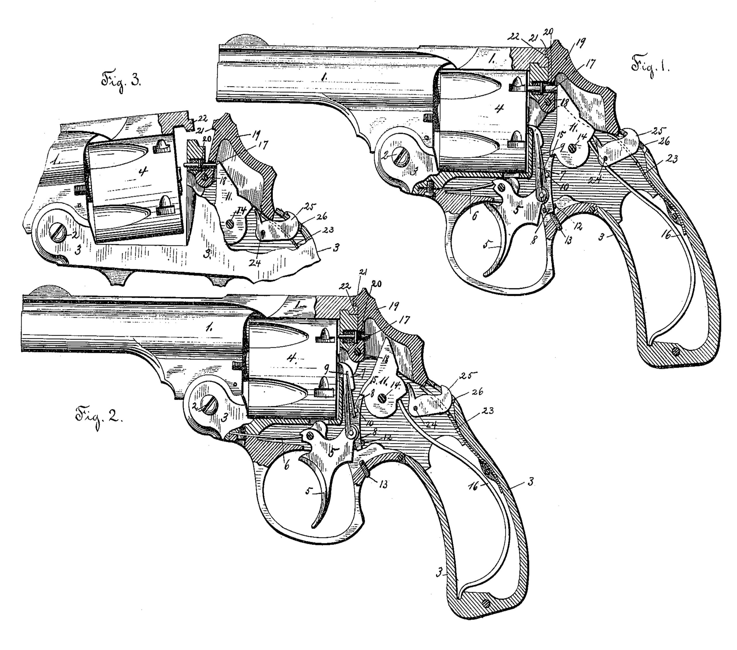
Referring to the drawings, Figure 1 is a side elevation, partly in section, of a revolver embodying my improvements. The several parts of the cocking and firing mechanism are shown in their normal position with the hammer locked. Fig. 2 corresponds with Fig. 1, except that the hammer is shown unlocked and partially cocked and the trigger and parts connected therewith partially operated preparatory to discharging the revolver; and Fig. 3 is a detached section of the revolver to illustrate how the hammer is automatically unlocked when the barrel-catch is drawn back to allow of the barrel being tilted on the stock for the discharging or refilling of the cartridge-cylinder.
In the accompanying drawings, the barrel 1 is connected by a hinge-joint at 2 with the
stock or handle 3, and is adapted to be tilted thereon in the ordinary manner. A revolving cartridge-cylinder, 4, is supported and turns on its central stem secured in the barrel portion in any well-known manner.
The cocking and firing mechanism shown is of the ordinary construction in this class of revolvers, consisting of the trigger 5, pivoted in the stock, and an actuating-spring, 6, a pawl, 7, for revolving the cylinder, and a sear, 8, for cocking the hammer, both pivoted on the trigger 5 in the ordinary manner, and a spring, 9, secured at its upper end to the pawl 7, with its lower end acting against a pin, 10, on the sear 8. Said spring 9 serves to keep the pawl 7 in engagement with the ratchet-teeth on the rear end of the cylinder 4, and also to keep the upper end of the sear 8 in contact with the hammer 11.
In the present instance I have shown the sear 8 provided with an adjusting screw, 12, extending through the lower end thereof, with its inner end adapted to bear against the trigger in the process of cocking the hammer. (See Fig. 2.) The object of this is to provide for any wear or abrasion of the inner upper edge of the sear 8, and to cause the same to fit against and operate the hammer in the proper manner, notwithstanding any wear or abrasion of the sear. I have also provided an adjusting screw, 13, extending through the under side of the stock or handle 3, with its inner end adapted to bear against the lower end of the sear 8 when the parts of the firing mechanism are in their normal positions, (see Fig. 1,) for the purpose of holding the sear up in contact with the hammer at its upper end and provide for any wear or abrasion of the upper end of the sear, and also to prevent any looseness. or rattling of the sear or trigger.
The hammer 11 is hung in the stock or handle on a pin, 14, and is provided with a notch or projection, 15, with which the sear 8 engages in the usual manner. A mainspring, 16, is connected with the hammer 11 in the ordinary manner, and the upper end of the hammer is adapted to strike against the firing pin 17 of ordinary construction.
In the upper part of the stock 3 is pivoted on a pin, 18, in front of the hammer 11, the barrel-catch 19, which is cut out upon its interior surface to permit of the upper end of the hammer 11 freely moving back and forth within the same. A hole, 20, is made in the forward part of the catch 19, through which the firing-pin 17 extends. The upper end of the catch 19 is provided with a projection or lip, 21, adapted to engage with a corresponding notch, 22, in the end of the barrel portion to hold the barrel down upon the stock. A spring, 23, forked at its upper end, is secured within the stock or handle and presses at its upper end against the lower end of the catch 19, and serves to keep the same up in its proper position. Said catch 19 acts against the spring 23 when it is drawn back, as shown in Fig. 3.
Just back of the hammer 11, and at the lower rear end of the catch 19, is hung or pivoted within the stock or handle 3, on a pin, 24, the lock-lever 25, with its outer end extending through a hole, 26, in the upper side of the handle, just at the rear of the barrel-catch, and its inner end adapted to engage with the hammer 11 and lock the same when the outer end of the lock-lever 25 is tilted up; (see Figs. 1 and 3,) and to extend above the hammer and allow the free cocking thereof when the outer end of the lock-lever 25 is tilted down. (See Fig. 2.)
The lock-lever 25 is so constructed and hung in the stock or handle 3 that when its outer end is drawn down so as to tilt up its inner end, as indicated in Fig. 2, it will not engage with the hammer 11 to lock the same, but will allow it to be freely cocked; but when the outer end of the lock-lever 25 is pushed up, as indicated in Fig. 1, the inner end of said lever will be tilted down to engage the hammer and prevent it from being cocked. The lock-lever 25 is hung in the stock or handle 8 in such a manner as to extend into the line or path of movement of the barrel-catch 19, so that when the barrel-catch 19 is drawn back to release the barrel portion and allow it to be tilted on the stock, as indicated in Fig. 3, the lower end of said catch 19 will bear against the lock-lever 25 outside of the pivot-point in such a manner as to tilt up the inner end of the lock-lever and unlock the hammer, so that when the barrel and stock are brought together again the hammer will be unlocked and the revolver ready to be discharged. By pressing up the outer end of the lock-lever 25 the hammer may be securely locked and the revolver prevented from discharging.
It will thus be seen from the above description, in connection with the drawings, that by means of the lock-lever 25, pivoted within the handle and with its outer end extending through the upper side of the handle where it can be easily operated by the thumb of the operator, I have provided a very simple and effective means for the locking and unlocking of the hammer of the revolver, and, further, that by means of said lock-lever 25 extending into the path of movement of the barrel-catch 19, in connection with said barrel-catch 19, I have provided for the automatic unlocking of the hammer every time the barrel-catch is drawn back to release the barrel portion and allow it to be tilted on the stock.
If preferred, the details of construction of the cocking and firing mechanism may be varied somewhat from what is shown in the drawings and above described, and the adjusting-screws employed in connection with the sear for operating the hammer may be dispensed with.
My improvements may equally well be applied to other kind of fire-arms, and I do not limit myself to their use in revolvers.
Having thus described my invention, what I claim as new, and desire to secure by Letters Patent, is—
1. In a firearm a hammer-locking lever pivoted in the upper part of the handle, with its inner end adapted to engage the hammer to lock the same and its outer end extending through the handle and into the path of movement of the barrel-catch, for the purpose stated, substantially as shown and described.
2. In a fire-arm, the combination, with the barrel-catch hung in the upper part of the handle, of a hammer-locking lever pivoted within the handle, with its inner end adapted to engage the hammer to lock the same and its outer end extending into the path of movement of the barrel-catch to be engaged thereby to unlock the hammer, in the manner substantially as shown and described.
3. In a fire-arm, the combination, with the barrel-catch hung in the upper part of the handle at a point in front of the hammer and cut out upon its inner surface to allow of the hammer moving freely back and forth within said catch, and said hammer hung within the handle of a hammer-locking lever pivoted within the handle, with its inner end adapted to engage and lock the hammer and its outer end extending into the path of movement of the barrel-catch, for the purpose stated, substantially as set forth.
4. In a fire-arm, the combination, with a sear for cocking the hammer, provided with an
adjusting-screw extending through the lower end thereof to engage the trigger of an adjusting screw secured in the stock or handle to bear at its inner end against the lower end of said sear, for the purpose stated, substantially as shown and described.
5. In a fire-arm, the combination, with the moe for cocking the hammer, of an adjusting-screw secured in the stock or handle and adapted to bear at its inner end against the lower end of said sear, for the purpose stated, substantially as shown and described.
MARTIN BYE.
Witnesses:
JOHN C. DEWEY,
CLARENCE M. DICKINSON.