
US 373893
UNITED STATES PATENT OFFICE.
JOHN C. HOWE, OF WORCESTER, MASSACHUSETTS, ASSIGNOR TO SULLIVAN FOREHAND, OF SAME PLACE.
REVOLVING FIRE-ARM.
SPECIFICATION forming part of Letters Patent No. 373,893, dated November 29, 1887. Application Filed April 1, 1887. Serial No, 233,251. (No model.)
To all whom it may concern:
Be it known that I, JOHN C. HOWE, a citizen of the United States, residing at Worcester, in the county of Worcester and State of Massachusetts, have invented certain new and useful Improvements in Revolving Fire-Arms; and I do hereby declare that the following is a full, clear, and exact description thereof, which, in connection with the drawings making a part of this specification, will enable others skilled in the art to which my invention belongs to make and use the same.
My invention relates to improvements in revolving fire-arms; and it consists in certain. novel features of construction and operation of the mechanism for cocking and firing the same, and also or the mechanism for securing the barrel portion to the stock, to prevent the discharge of the fire-arm in ease the same are not properly secured together.
The object of my invention is to construct a revolving fire-arm in such a manner that it cannot be discharged by drawing back the trigger, as is customary in self-cocking revolvers, but requires the pressing in of a button extending through the handle or stock to release the hammer alter it is cocked and allow the same to operate to discharge the fire-arm. By my improved construction I prevent the hammer from being operated to discharge the fire-arm, except by the pushing in of a button extending through the handle; but T do not prevent the trigger and connecting mechanism from being operated to cause the cylinder to be revolved and the hammer to be fully cocked preparatory to firing, for this can be done, as in fire-arms of the ordinary construction, without regard to the button for operating, the hammer.
A second feature of my invention relates to my improved manner of securing the barrel portion, adapted to be tilted, on the stock to the stock, so as to prevent the fire-arm from being discharged in case the stock and barrel portion are not properly secured together, will be hereinafter fully described.
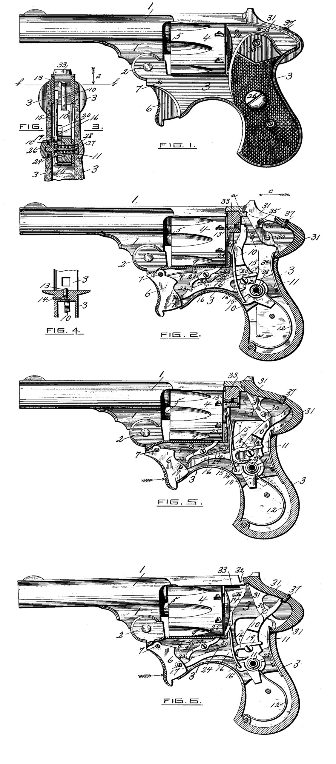
Referring to the drawings, Figure 1 is a side elevation of a revolver embodying my improvements. Fig. 2 is the revolver shown in Fig. 1. with the stock shown in section to more clearly illustrate my improvements. The parts are shown in their normal positions. Fig. 3 is a vertical section through a portion of the stock of the revolver, taken at line a a, Fig. 2, looking in the direction of arrow c, to illustrate the construction and operation of the mechanism for releasing the hammer after it is cocked and allowing the same to operate. Fig. 4 is a detached view, taken on line b b, Fig. 3, looking in the direction of arrow d, same figure, to illustrate the manner of holding the firing-pin in place. Fig. 5 corresponds with the view shown in Fig. 2, except that the several parts of the cocking and firing mechanism are shown in their opposite positions ready for the discharge of the revolver by pushing in the button (not shown) to release the hammer and allow it to operate. The dotted lines represent the hammer after it is released, and also the position of the lever connecting the hammer with the trigger; and Fig. 6 represents the barrel portion not properly secured to the stock, and the manner of preventing the hammer from being cocked, and the discharge of the revolver by pushing in the button to release the hammer, as will be hereinafter fully described.
In the accompanying drawings, the barrel 1 is connected by a hinge-joint at 2 with the stock 3, and is adapted to be tilted thereon in the ordinary manner. The revolving cylinder 4 is supported and turns on its central stem, 5, secured in the barrel portion in any well-known manner. The stock or frame 3 has in this instance the trigger 6 in its lower forward part pivoted on a pin, 7. A spring, 8, secured at 9 to the stock 3, with its free end pressing upon the upper part of trigger 6 back of its pivot-point, serves to restore the trigger to its normal position, Fig. 2, after it has been operated. The hammer 10 is pivoted on a tubular stud, 11, screwed into the under side of the stock or frame 8. (See Fig. 3.) The mainspring 12 is connected with the hammer 10 in any ordinary way to cause the same to operate.
The upper end of the hammer 10 is adapted to engage with the head of the firing-pin 13, (see Fig. 2,) of any ordinary construction, supported in the stock 3, and in this instance held in place, by a pin, 14, secured in the stock and entering into a circumferential groove made in the firing-pin 13. (See Fig. 4.)
A lever or pawl, 15, is secured at its lower end to the hammer 10, and is adapted to engage at its upper end with the ratchet-teeth on the rear end of the cylinder 4, to cause said cylinder to revolve in the usual manner, as hammer 10 is tilted back or cocked. (See Figs. 2 and 5.)
The trigger 6 is connected with the hammer 10 by means of a lever, 16, pivoted at one end by a pin, 17, to said trigger, and provided with a notch, 18, (see dotted lines, Fig. 5,) at its other end adapted to engage with a screw or stud, 19, secured in or formed on the hammer 10. In this instance the surface of the hammer 10 is cut out, as indicated at 20, Figs. 2 and 3, so that the upper surface of the lever 16 will be flush with the upper surface of the hammer and allow said lever 16 to pass freely under the pawl 15. (See Fig. 3.) The cylinder-locking lever 21 is pivoted at 22, and is operated to release the cylinder and allow the same to be revolved by the pawl 15 in the ordinary manner as the hammer 10 is cocked by means of a cam or projection, 23, upon the upper edge of the lever 16. A spring, 24, secured at 25, serves to keep the lower end of the lever 21 in contact with the lever 16, to be operated by the same, and at the same time serves to force down the lever 16 at its free end, so that the notch 18 will engage with the stud 19, as before described.
From the above description, in connection with the drawings, it will be readily seen that by drawing back the trigger 6 the cylinder-locking lever 21 is operated to release the cylinder by means of the projection 23 on the lever 16. The hammer 10 is cocked through the intervention of the lever 16, connecting it with the trigger 6 in the manner above described, and the pawl 15, connected with the hammer, is operated to revolve the cylinder 4, and the several parts of the mechanism assume the position shown by full lines, Fig. 5.
The notch 18 in the lever 16, engaging with the stud 19 on the hammer 10; as above described, holds said hammer in its backward position when it is cocked, and will so hold it and prevent it from being operated to discharge the fire arm until some supplementary mechanism is brought into action to raise the free end of the lever 16 and disengage it from the stud 19 on the hammer 10, thus releasing said hammer and allowing the mainspring 12 to act to operate the same to discharge the fire-arm, as shown by dotted lines, Fig. 5.
I will now proceed to describe the mechanism for raising the free end of the lever 16 or disengaging the notch 18 therein from the stud 19 on the hammer 10 to release the same and allow it to operate to discharge the fire-arm.
I have shown in the drawings one way of constructing said mechanism; but it will be understood that I do not limit myself to this construction, as any equivalent way may be employed in lieu of that shown. Said mechanism for raising the free end of the lever 16 and releasing the hammer 10 after it has been cocked, to allow it to operate, is most clearly illustrated in Fig. 3 of the drawings, and a clear understanding of the construction and operation of said mechanism will be obtained by referring to said Fig. 3, in connection with Fig. 5. The handle of the stock 3 is provided with an opening extending through the same on the left-hand side thereof, to allow the push-button 26 to extend through the handle at one side, with its outer surface projecting slightly above the surface of the handle. (See Figs. 1 and 2.) In this instance the head of the push-button 26 is adapted to fit into a circular opening made in the left side of the handle, and the shank of said button extends through the side of the handle and is provided with an internal screw-thread adapted to engage with a screw-thread upon the end of a pin, 27, forming the central stud or spindle of the button 26 and moving in and out with said button. The pin 27 extends through the tubular stud 11, upon which the hammer 10 is pivoted, as hereinbefore described, and a small spiral spring, 28, encircles said pin 27 and is inclosed within the stud 11. Said spring 28 bears at its lower end against a shoulder or flange upon the interior of the tubular stud 11, and at its upper end against the inner surface of the circular head or flange 29, formed upon the upper part of the pin 27. The upper surface of the head 29 comes in contact with the interior surface of the side of the handle (see Fig. 3) and limits the action of the spring 28. By pushing in the button 26 against the action of the spring 28 the pin 27 and the head 29 thereon move with it. The lower part of the head 29 is made beveled or slightly tapering, (see Fig. 3,) for the purpose to be hereinafter described.
The lever 16, connecting the trigger 6 with the hammer 10, as above described, has a curved arm or projection, 16’, extending out from its free end, and the end of said arm 16’ is adapted to extend directly under the lower tapering edge of the head 29 on the pin 27 when the trigger is drawn back and the hammer fully cocked. (See Figs. 3 and 5.) By pushing in the button 26 when the hammer is cocked the tapering edge of the head 29 on the pin 27 comes in between the stud 11 and the arm 16’ (see Fig. 3) and forces said arm and the lever 16 up, (see dotted lines, Fig. 5,) thus tripping the lever 16 and releasing the notch 18 in said lever from the stud 19 on the hammer 10, and allowing said hammer to operate to discharge the fire-arm.
From the above description, in connection with the drawings, the operation of the mechanism for releasing the hammer or allowing it to operate after it has been cocked, by pushing in the button 26, extending through the handle skilled in the art.
A continuous firing of the revolver until all of the fire-arm, will be understood by those the cartridges are discharged is obtained by keeping the button 26 pushed in, when the fire-arm acts in the same manner and can be discharged with a rapidity equal to or greater than self-cocking fire-arms of the ordinary construction.
It will be understood that the details of construction of my improved mechanism for cocking and discharging a revolving fire-arm may be varied somewhat from what I have described without departing from the principle of my invention, and the same may be adapted to be employed in connection with revolving firearms of any ordinary construction.
The push-button, for releasing the hammer after it has been fully cocked, instead of extending through the side of the hammer, as above described; and illustrated in the drawings, may extend through the rear or front part of the handle and be adapted to operate to release the hammer in substantially the manner hereinbefore set forth.
I will now describe the second feature of my improvements in revolving fire arms, relating to the manner of securing the barrel portion to the stock, so as to prevent, in case they are not properly secured together, (see Fig. 6,) the full-cocking of the hammer 10 and the operation of the same by pushing in the button 26, as above described.
In the upper part of the stock 3 is i pivoted, by means of pins 30, extending through each side thereof, the barrel-catch 31, provided with a hook at its forward end to extend into and engage a bevel-slot, 32, made in the rear end of the barrel portion 1 to secure said barrel portion to the stock. A conical or tapering projection, 33, is formed upon the upper part of the stock 3, adapted to enter into and engage a corresponding depression made in the barrel portion when said barrel portion is in its proper position to be secured to said stock. (See Fig.2.) A spring, 34, is secured within the handle or stock 3, and presses against the lower end of the catch 31 and depresses the upper end of said catch causing the hook thereon to engage with the beveled slot 32 in the barrel portion when the same is depressed sufficiently. A small pin or screw, 35, secured in the stock 3 and extending through an elongated hole, 36, in the catch 31, (see Fig. 2,) limits the backward-and-forward tilting motion of said catch. The catch 31 is slotted longitudinally or cut out upon its interior surface, as indicated in Figs. 2, 5, and 6, to allow of the hammer 10 passing freely back and forth within said catch 31. A stop-pin or screw, 37, extends through the upper part of the catch 31, with its inner end projecting slightly beyond the interior surface of said catch. The object of the pin 37, used in connection with the barrel-catch 31 and the hammer 10, is to prevent the full-cocking and operation of said hammer to discharge the fire-arm in case the barrel portion is not properly secured to the stock, as shown in Fig. 6.
It will be understood that the hammer must be fully cocked in order to be released or allowed to operate by pushing the button 26, as above described.
When the barrel portion and the stock are properly secured together by means of the catch 31, as shown in Figs. 2 and 5, the end of the hammer 10 will pass freely by the end of the pin 37; but when the barrel portion is not properly secured to the stock, as indicated in Fig. 6, the rear end of the barrel portion presses against the hooked end of the catch 31 and forces it back, and causes the end of the pin 37 to come in contact with the upper end of the hammer 10 as the same is forced back by the operation of the trigger, preventing said hammer from being fully cocked, as indicated in said figure, and thus preventing the push-button 26 from releasing said hammer or allowing it to operate, by reason of the curved arm 16’ not being drawn back sufficiently far to be acted upon by the head 29 on the pin 27 of the batton 26 in the manner above described.
In lieu of the pin 37, a knob or projection may be formed upon the inner surface of the catch 31 to accomplish the same result as described above. The value of this feature of my improvements will be readily appreciated by those skilled in the art, for without this provision to prevent the fall cocking of the hammer and the discharge of the fire-arm when the barrel portion is not properly secured to the stock serious accidents might occur by the tilting forward of the barrel, caused by the operation of the hammer and the discharge of cartridge, either accidentally or otherwise.
The great advantage of my improvements in the mechanism for cocking and firing revolving fire-arms will be readily apparent to those skilled in the art.
I am enabled to prevent the hammer from being accidentally or inadvertently operated to discharge the fire-arm after it has been cocked by means of the trigger, for a separate and distinct operation is required to operate the hammer after it has been cocked—namely, the pushing in of a button extending through the handle of the fire-arm.
I can obtain a continuous discharge of the fire-arm, as in fire-arms of the ordinary construction, by simply holding the button pressed in and operating the trigger.
Having thus described my improvements in fire-arms, what I claim as new, and desire to secure by Letters Patent, is—
1. In a fire-arm, the combination, with the trigger pivoted in the stock, a lever connecting said trigger with the hammer to cock the same, and said hammer, of a push-button extending through the handle and provided with an actuating-spring, a central spindle, and an enlarged bead adapted to engage with and operate the lever to release the hammer after it is cocked and allow the same to operate, substantially as set forth.
2. The combination, with the trigger, a lever, 16, connecting said trigger with the hammer, and said hammer provided with a pin or stud to engage said lever, and a mainspring for operating said hammer, of a push-button provided with an actuating-spring and a central spindle, and an enlarged head adapted to engage with the lever 16, to operate the same to release the hammer after it has been cocked and allow it to operate, substantially as set forth.
3. The combination, with a lever, 16, connecting the trigger with the hammer and provided with a cam or projection, 23, to engage and operate the lower end of the cylinder-locking lever 21, of said cylinder-locking lever 21, operated by said lever 16 in the manner set forth, and an actuating-spring, substantially as shown and described.
4. In a fire-arm, a catch for securing the barrel portion to the stock, provided with a pin or knob against which the hammer strikes to prevent the full-cocking of the same in case the stock and barrel portion are not properly secured together, substantially as set forth.
5. In a fire-arm, the combination, with the stock and barrel portion adapted to be tilted on the stock, of a barrel-catch pivoted in the stock for securing the barrel portion thereto and provided with a stop pin or knob to prevent the full-cocking and operation of the hammer. In case the barrel portion and the stock are not properly secured together substantially as set forth.
6. In a fire-arm, the combination, with a catch pivoted in the stock and provided with a stop pin or knob, of the hammer adapted to strike against said pin to prevent the full-cocking and operation of said hammer in case the stock and barrel portion are not properly secured together, substantially as set forth.
7. In a fire-arm, a catch for securing the barrel to the stock, hung on a pin extending through the stock and adapted to be swung thereon and to extend through the stock to form the upper exposed edge thereof and provided with an actuating-spring, substantially as shown and described.
8. In a fire-arm, a barrel-catch, 31, pivotally hung on a pin, 30, in the stock and provided with an actuating-spring, 34, and cut out upon its interior surface to permit of the hammer passing back and forth within the same, substantially as shown and described.
JOHN C. HOWE.
Witnesses:
JOHN C. DEWEY,
M. RALPH DRYDEN.