
US 370926
UNITED STATES PATENT OFFICE.
HOMER M. CALDWELL, OF WORCESTER, MASSACHUSETTS, ASSIGNOR TO GILBERT H. HARRINGTON AND WILLIAM A. RICHARDSON, BOTH OF SAME PLACE.
REVOLVING FIRE-ARM.
SPECIFICATION forming part of Letters Patent No, 370,926, dated October 4, 1887.
Application filed March 22, 1887. Serial No, 232,198. (No model.)
To all whom it may concern:
Be it known that I, HOMER M. CALDWELL, a citizen of the United States, residing at Worcester, in the county of Worcester and State of Massachusetts, have invented certain
new and useful Improvements in Fire- Arms, of which the following, together with the accompanying drawings, is a specification sufficiently full, clear, and exact to enable persons
skilled in the art to which this invention appertains to make and use the same.
This invention relates to that class of fire-arms or revolvers in which the cylinder or
cartridge-chamber block is supported in connection with the barrel, and wherein the barrel and frame are connected by a hinge or joint, so that the barrel can swing thereon or break down for exposing the breech of the chambers for extraction of cartridge-shells and insertion of cartridges when charging.
This invention is applicable to arms in which either automatic or non-automatic extractor
mechanism is employed.
The object of my present invention is to provide a simple, practical, and convenient
device for retaining the cylinder or cartridge-chamber block in proper position or relation to the barrel when the breech is opened, which device, while securely retaining the cylinder during the ordinary manipulation of the arm for charging, will also permit of the ready and convenient removal of the cylinder from its support for the purpose of cleaning, and to facilitate the convenient separating and assembling of the parts whenever desired.
Another object of my invention is to provide a cylinder-retaining catch in connection
with the barrel-extension, having in combination therewith a device for locking said catch in its positions of adjustment both in and out of engagement with the cylinder; also, to provide a cylinder-retaining catch disposed beneath or partially within the barrel-catch and pivoted in conjunction therewith and combined with a locking device, whereby the barrel-catch is retained inoperative when the cylinder-retaining catch is out of engagement with the cylinder, as more fully hereinafter explained.
These objects I attain by mechanism the nature and operation of which are illustrated in the drawings and explained in the following description, the particular subject-matter claimed being hereinafter definitely specified.
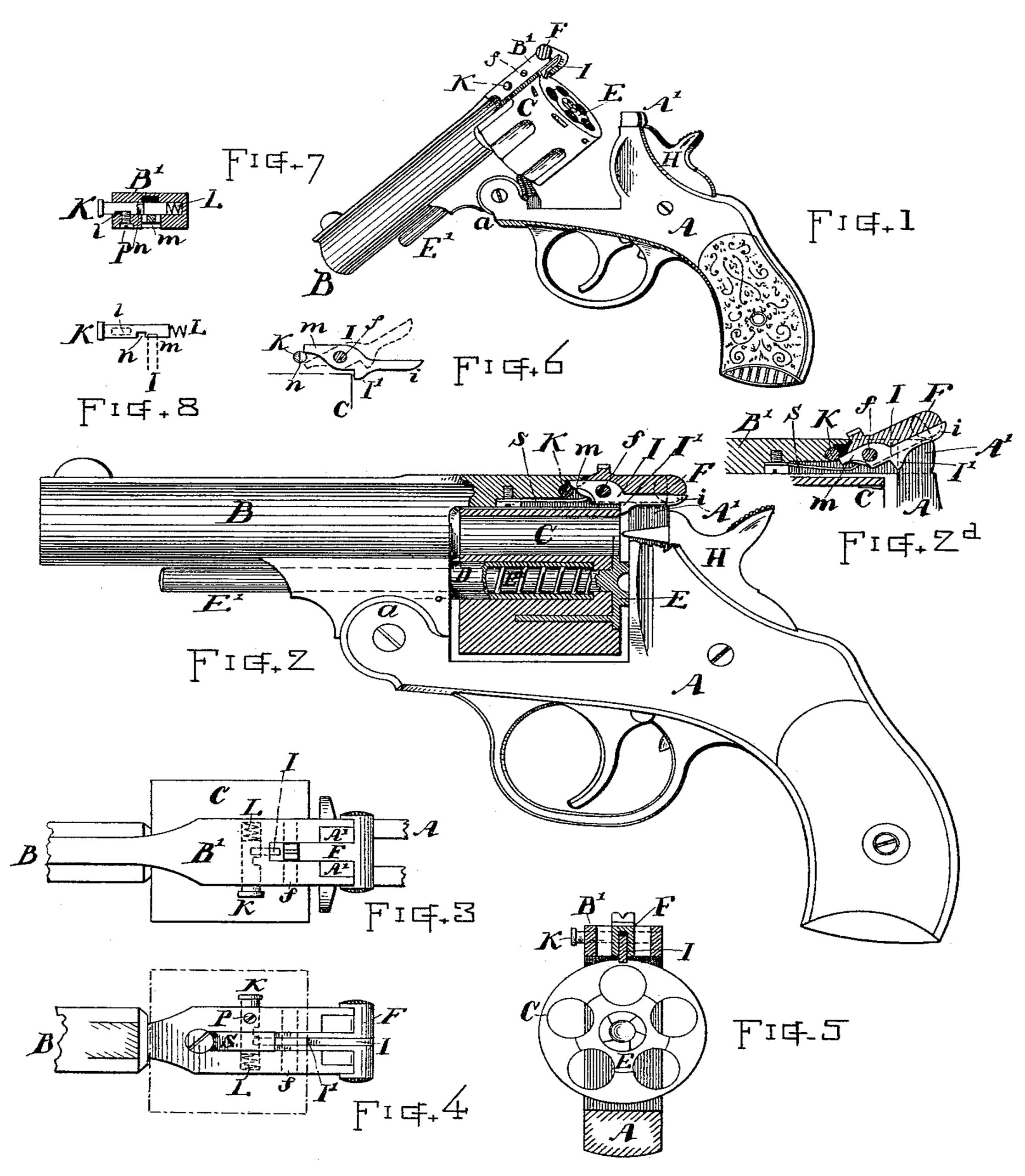
In the drawings, Figure 1 is a perspective view of a revolver or fire-arm embracing my invention. Fig. 2 is a side view of the same with the cylinder, barrel-extension, and barrel-catch shown in longitudinal section. Fig. 2a shows the catches in elevated position. Fig. 3 is a top view of the barrel-extension and catch mechanisms. Fig. 4 is a bottom view of the same. Fig. 5 is a vertical transverse section at the rear of the cylinder, looking toward the front. Fig. 6 is a detail view of the retaining-catch devices separate from the other parts. Fig. 7 is a transverse section of the barrel-extension, showing the locking device; and Fig. 8 is a plan view of the locking-stud separately.
In reference to parts, A denotes the frame; B, the barrel connected to the fore end of said frame by a hinge-joint of ordinary form, as a.
C indicates the chamber-block or cylinder, in the present instance mounted to revolve on
the cylindrical quill D, fixed to the barrel-support.
E denotes the extractor, having a spindle, E’, extending through the quill in the well-known manner and arranged for forcing out the cartridge-shells from the chamber by the
backward pressure of its spindle when the breech is opened; or, if preferred, said extractor may be connected with a toothed segment or automatic actuating devices at the point of hinging for working the extractor as the barrel swings or breaks down, as heretofore employed in fire-arms of this class.
B’ indicates the barrel-extension projecting rearward over the top of the cylinder and joining the upwardly-projecting part A’ of the frame above the seat of the hammer H, and adapted to be locked thereto by the barrel-catch F, which latter is pivoted on the pin f, so as to swing over the projecting ends A’ of the frame for locking and securely retaining the barrel-extension and frame together when in position for firing, and to swing off from said ends A’ to permit the breaking down of the barrel for opening the breech. Said barrel-catch F is made substantially as heretofore employed, except that in my improvement it is provided with a longitudinal groove on its under side.
Within the barrel-catch, and preferably pivoted on the same pin f, I arrange a cylinder-retaining catch, I, made substantially in the form indicated in Figs. 2 and 6, and having a projection or tooth, I’, that engages the rear corner or an angle on the cylinder or chamber-block and prevents said cylinder from sliding rearward on its supporting-quill D when the breech is opened. The supporting axis or quill D is made simply smooth and straight, so that the cylinder can slip on and off without obstruction when the catch I is raised. The catch I has an arm, i, extending rearward to, or nearly to, the end of the barrel-catch, and with a forwardly-projecting end, m, that engages with a locking device or stud, K, disposed transversely within the barrel-extension, with its head projecting from the side thereof sufficiently to be conveniently pressed in with the thumb.
The stud K is provided with a notch, n, in its rear side, through which notch the end m
of the retaining-catch I can swing. Said notch n is retained normally out of line with the catch by the action of a spring, L, inserted in the hole beneath the end of the stud K. The stud is retained in the barrel-extension by means of the screw P, (see Fig. 7,) the end of which engages with a recess, J, in the bottom of the stud, which recess is of sufficient length to permit the required movement of the stud
for carrying the notch n into and out of line with the end m of the retaining-catch I, while limiting the movement of the stud as required. When the end m of the retaining-catch I is above the stud, the tooth or projection I’ is retained in position for confining or retaining the cylinder C and for holding it against the backward pressure of the extractor when forcing out the cartridge-shells; but when the end m of the retaining-catch is adjusted below the stud K said catch is retained, with its tooth I’ elevated, or in position to permit the cylinder to be removed and replaced without interference therewith. (See Fig. 2a and dotted lines, Fig. 6.)
When the retaining-catch I has been raised and is locked back with its end m below the stud K, the barrel-catch F is also retained in elevated position; hence the barrel-extension B’ cannot be locked to the end A’ of the frame until the cylinder-retaining catch I is released and lowered.
For elevating or lowering the cylinder-retaining catch I, the stud K is pressed with the thumb, so as to bring the notch n in line with the end m of the catch. The retaining-catch I can be released only by lifting up its end i with the thumb while the stud K is pressed inward; but said catch I will, however, return to position, when released, by depressing the stud K, if being forced down by the pressure of the spring S acting on the barrel-catch F, and the barrel-catch rests upon the top of the arm i of the retaining-catch.
I am aware that fire-arms have heretofore been made in which a projection is formed on
the under side of the barrel-catch and integral therewith for engaging the cylinder; but such a device does not effect the results attained by my invention, for the reason that by such heretofore-employed method the cylinder is released every time the barrel-catch is raised for unlocking the barrel-extension from the frame, whereas in my invention the cylinder is retained, except when intentionally released by the raising of the retaining-catch, and said catch is by its locking device held either in or out of engagement so long as desired, while the cylinder can be conveniently removed and replaced as often as necessary without any inconvenience from the catch. This is a great advantage, and enables me to construct the quill plain and smooth, so that the cylinder can be slipped on and off readily, requiring no other means of connecting than the axial support and the retaining-catch I.
What I claim as of my invention, and desire to secure by Letters Patent, is—
1. The combination, with the frame, barrel-extension, cylinder, and barrel-catch, of the cylinder-retaining catch located within or beneath said barrel-catch, and consisting of a lever pivoted on a transversely-disposed stud, in connection with the rear part of the barrel-extension for upward and downward swinging action, having a downwardly-projecting lug that engages the cylinder to retain it in proper relation to the barrel, substantially as hereinbefore set forth.
2. The combination, with the frame, barrel-extension, and cylinder, of a longitudinally-recessed barrel-catch, a cylinder-retaining catch disposed partially within said barrel-catch and pivoted to have upward and downward swinging action, and a locking device, substantially as described, adapted to engage either above or below the end of said retaining-catch for locking it in either outward or inward positions of adjustment, as set forth.
3. The combination, with the frame, barrel-extension, and cylinder, of the barrel-catch and a cylinder-retaining catch unattached to said barrel-catch, both supported on the same transversely-disposed pivot-pin, in connection with the rear part of the barrel-extension, to swing upward and downward at their rear ends, substantially as and for the purpose set forth.
4. The combination, with the frame, barrel-extension, and cylinder, of the barrel-catch and cylinder-retaining catch pivoted on a transversely-disposed stud near the rear end of the barrel-extension, and having an end, i, that extends beneath said barrel-catch, and a forwardly-extended end, m, and the locking device or stud fitted in the side of the barrel-extension and adapted to slide over said forward end of the retaining-catch when the catches are raised, substantially as described, whereby said barrel-catch is held elevated while said retaining-catch is in elevated position.
5. The combination, with the barrel-extension, longitudinally-grooved barrel-catch, and cylinder, of the cylinder-retaining catch I, disposed partially within said barrel-catch and pivoted in connection with the barrel-extension for upward and downward swinging action, the spring S for depressing said barrel-catch and retaining-catch, and the reciprocating locking-stud K, fitted laterally in the barrel-extension adjacent to said retaining-catch, and when in normal position engaging beneath the front end of the same, as described, whereby said retaining-catch is locked in depressed position while the barrel-catch is free to be elevated, substantially as set forth.
6. The combination, with the frame having the projections A’, the barrel hinged to the fore end of the said frame and provided with the extension B’, and the cylinder C, supported on the quill D, of the barrel-catch having a longitudinal recess iu its under surface, the retaining-catch I, having a tooth or projection, I’, that engages said cylinder, and a forwardly-projecting end, m, said retaining-catch being disposed in said longitudinal recess, and with said barrel-catch pivoted on the stud f, the reciprocating stud K, having the passway-notch n, disposed laterally through the side of the barrel-extension and engaging the forward end, m, of the retaining-catch, and the spring L, substantially as and for the purpose set forth.
Witness my hand this 21st day of March, A. D. 1887.
HOMER M. CALDWELL.
Witnesses:
CHAS. H. BURLEIGH,
FRED H. DANIELS.