
US 368599
UNITED STATES PATENT OFFICE.
JOHN M. MARLIN, OF NEW HAVEN, CONNECTICUT.
REVOLVER.
SPECIFICATION forming part of Letters Patent No. 368,599, dated August 23, 1887.
Application filed March 28, 1887. Serial No. 232,766. (No model.)
To all whom it may concern:
Be if known that I, JOHN M. MARLIN, of New Haven, in the county of New Haven and
State of Connecticut, have invented a certain new and useful Improvement in Revolving Fire-Arms, of which the following is a specification.
My invention relates to revolving fire-arms; and it consists of certain new and useful constructions and combinations of the several parts thereof, substantially as hereinafter described and claimed.
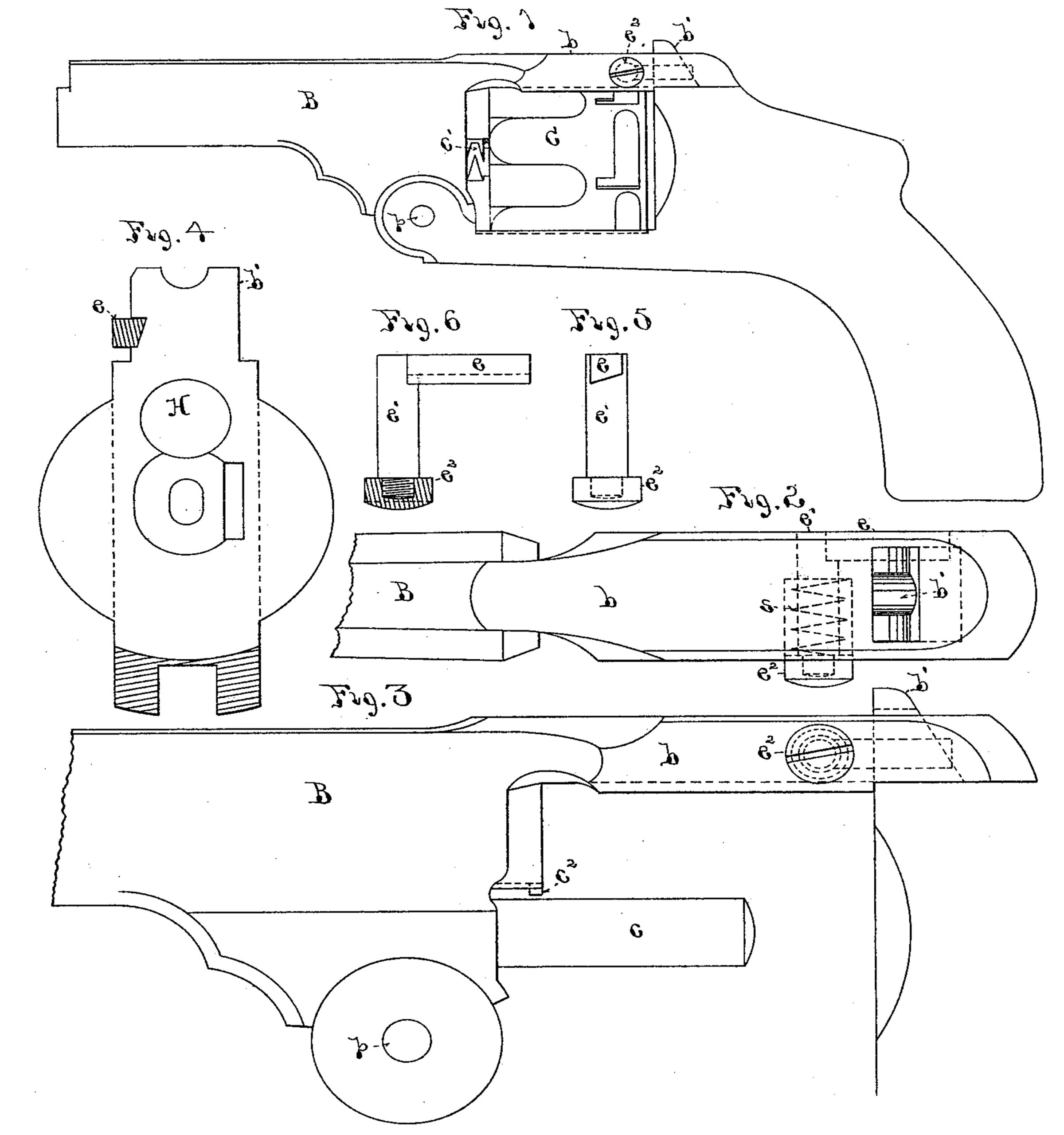
In the drawings, Figure 1 is a side elevation of a revolving fire-arm constructed according to my invention. Fig. 2 is an enlarged top plan view of a portion of the same. Fig. 3 is an enlarged side elevation of a portion of the same. Fig. 4 is an enlarged end view of the breech portion of the same from the dotted line y y of Fig. 1. Figs. 5 and 6 are detail views, the latter partly in section, of the barrel-locking latch.
B is the barrel of the arm, having an extension, b, which projects rearward over the cylinder. Underneath the barrel it has a projection, in which is located the pivot p, by which it is hinged to the frame at that point in the usual manner. A stud, b’, projects upward from the frame and passes through a mortise in the extension b. The cylinder C revolves on the pin c, fixed beneath the barrel. It has a grooved collar, c’, on a tubular extension at its front end, and by passing the pin c2 on the barrel through the groove of this sleeve the cylinder will be seated on its pin c and be held there until removed by turning it backward and passing the pin outward through the groove.
H is the aperture in the breech, Fig. 4, through which the hammer strikes the cartridges in the cylinder.
In one side of the stud b’, I form a notch to receive the latch e, as shown in Fig. 4, and in dotted lines in Figs. 1, 2, and 3. This latch consists of a straight bar of metal with an acute-angled edge to enter the notch in stud b’, and its inner face beveled or inclined downward and outward to allow it to spring past the stud in locking the barrel to the frame, as hereinafter described. The upper corner of the stud is also beveled off, as shown in Fig. 4, to accomplish the same purpose. The latch e is seated in a recess formed longitudinally in the side face of the extension b, and at its forward end is firmly attached to the bolt e’, at right angles to it, the latter extending transversely through the extension b, (a slot or hole being made through the latter for that purpose) and projecting outward beyond its opposite face. The bolt e’ is screw-threaded upon this projecting outer end, and the head e2 is there screwed upon it. Around the bolt e’, and extending inward, a chamber of the diameter of the outside of head e2 is made in the extension b, part way through it, and in this chamber a spiral spring, s, is placed, so as to bear against the head and hold the latch e in its recess and in engagement with stud b’, when the barrel is locked to the frame. The parts being adjusted as described, by pressing upon the head e2, the latch e will be forced outward and the barrel be unlocked from the frame. When the barrel is swung on its pivot p, so as to enter the stud b’ into its mortise in the extension b, the beveled face of the latch e striking against the stud will force it outward, and thus automatically lock it to the frame.
What I claim as new and of my invention is—
1. The combination of the frame-stud b’, formed with a notch in one side thereof, the
barrel-extension b, formed with a mortise to receive said stud, and a chamber in one side opposite to and corresponding with said notch, the latch e, seated in said chamber and adapted to engage with said notch, and the sliding bolt e’, attached to said latch at right angles thereto and extending transversely through said barrel-extension, and projecting beyond the opposite face of the same, substantially as described.
2. The combination of the frame-stud b’, formed with a notch in one side thereof, the barrel-extension b, formed with a mortise to receive said stud, and a chamber in one side opposite to and corresponding with said notch, the latch e, seated in said chamber and adapted to engage with said notch, and the sliding bolt e’, attached to said latch at right angles thereto and extending transversely through
said barrel-extension, the head e2, attached to the free end of said sliding bolt, and the spring s, seated in a chamber in said extension and bearing against said head, substantially as described.
JOHN M. MARLIN.
Witnesses:
C. F. DEMMER,
J. F. LAWLOR.