
US 137043
UNITED STATES PATENT OFFICE.
DAVID WILLIAMSON, OF GREENVILLE, NEW JERSEY.
IMPROVEMENT IN REVOLVING FIRE-ARMS.
Specification forming part of Letters Patent No. 137,043, dated March 18, 1873.
To all whom it may concern:
Be it known that I, David Williamson, of Greenville, in the county of Hudson and State of New Jersey, have invented certain new and useful Improvements in Fire-Arms; and I do hereby declare that the following is a full, clear, and exact description thereof, reference being had to the accompanying drawing, and to the letters of reference marked thereon which form a part of this specification.
My invention has for its object to improve the construction of the revolver, by using a less number of parts than generally brought together heretofore, and to furnish a device which shall be simple in construction, efficient in operation, durable in use, and not liable to get out of repair; and it consists in the construction, combinations, and arrangement of the different parts of device, as hereinafter more fully described and pointed out by the claims.
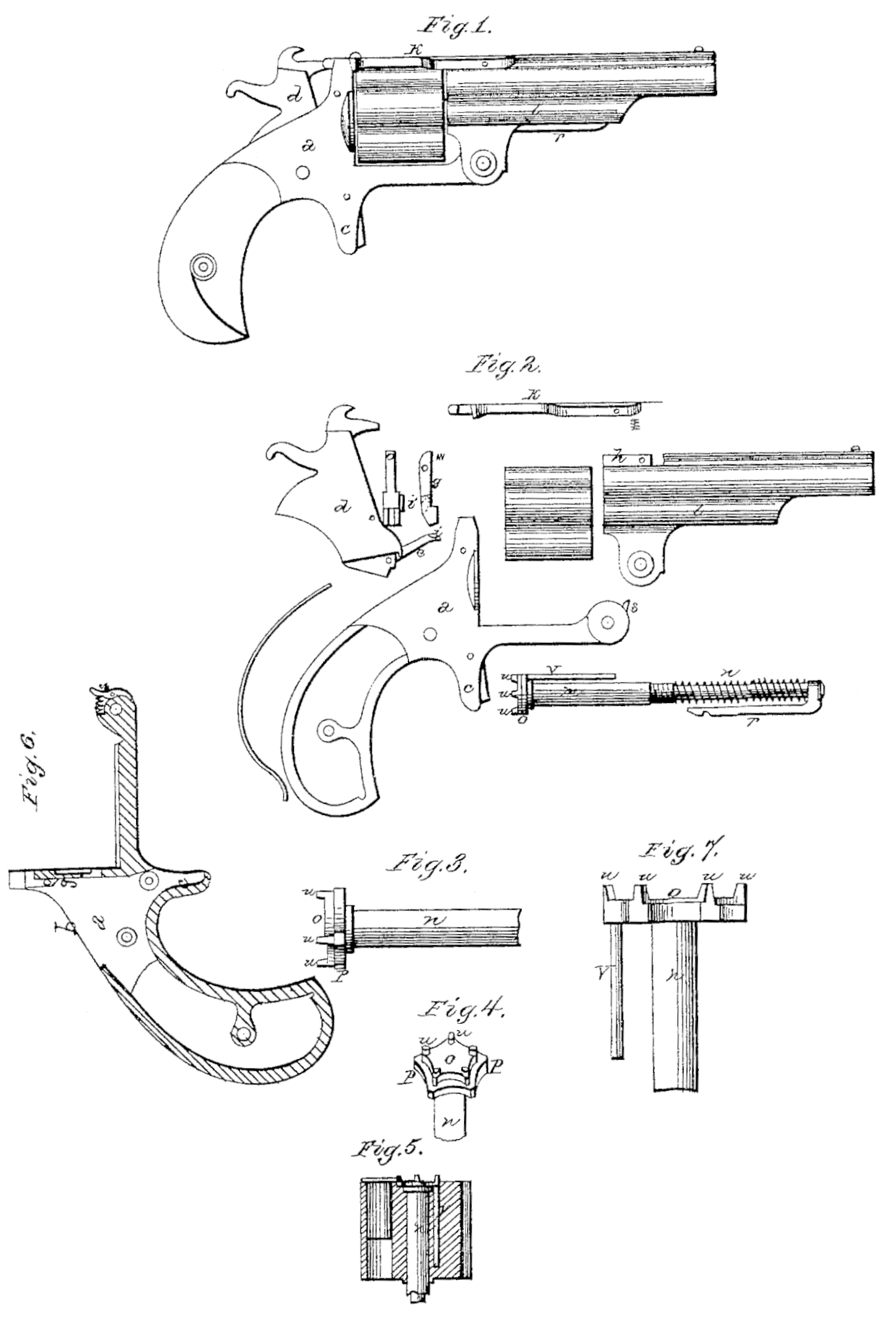
Referring to the drawing, Figure 1 represents a side elevation of a device embodying any invention. Fig. 2 is a detail view of the same. Figs. 3 and 4 are detail views of the retractor. Fig. 5 is a longitudinal section of the cylinder. Fig.6 is a longitudinal section of the frame, and Fig. 7 is an elevation of a portion of the retractor.
a represents the lock-frame, cast of metal in one solid piece, and having an opening, b, made through its top, instead of through the side, in the usual manner, for the reception of the lock, thereby dispensing with the lock plate on the side. As the shields for the triggers have heretofore been made, they have been cut through at the bottom, allowing the end of the trigger to project more or less, and which on the recoil is apt to cut or injure the knuckle. In order to obviate this difficulty, I make the shield c solid, having the trigger to project only from a recess in its front, thereby protecting not only the trigger-nose but the hand from injury. The hammer d is inserted downward through the top, and has pivoted to its side the spring-pawl e for revolving the cylinder, the pawl having on its side a cam, i, at or near the end. Pivoted inside of the opening b is the lock-bolt g, for locking the cylinder in place, and which has a groove cut in the front edge of the lower end for catching the projections by which the cylinder is revolved, and has a cam, i’, similar to the one on the pawl on its inner side. As the hammer is drawn back or cocked, the pawl e is moved forward and upward, causing the cam i on its side to catch against and under the cam i’ on the side of the lock-bolt, pressing the bolt back so as to release the cylinder and leave it free to revolve. As soon as the pawl has moved the cylinder far enough around, the cam i’ slips from the cam it, releasing the lock-bolt, which immediately springs forward again, and locks the cylinder in place. Pivoted to the top of the barrel, and having an elongated slot cut through its front end, so as to fit over the long bearing-stud h, is the spring lock-brace k, which locks the barrel in position by catching over a projection on the front of the lock-frame. This long bearing serves to brace the lock against side strains, and holds it firmly and securely in place. This peculiar construction of the lock-brace, as shown, and used in connection with the stud h, which is formed upon the barrel, renders the manufacture far more simple and less expensive, while at the same time the parts are held securely in position. Screwed into the bracket l of the barrel is a small tube, m, which serves as a pivot on which the cylinder revolves, and which has a flange upon its rear end for the purpose of holding the cylinder in place. If so desired, this flange may be omitted, and the cylinder be held by any equivalent device arranged in any other suitable position. Passing through the tube m, and projecting up in to the bracket l, is the extractor n, for either wholly or partially extracting the empty shells after firing. Upon the rear end is formed the head o, shown in Figs. 3 and 4, which has a flange, p, of uneven thickness extending around its side, and which fits in a recess in the rear end of the cylinder, in between the different chambers, so that the flanges of the cartridges when in position will bear upon its edge, as shown in Fig. 5. This flange being of an uneven thickness, when moved out ward it will act successively upon the cartridges, moving or starting one at a time, so as to prevent a great strain upon the pivot-pin or any other part of the mechanism. Pivoted to the front end of the extractor is a notched arm, r, with which the spring-pawl s, on the front end of the lock-frame engages, so that when the barrel is tilted this pawl will catch in the notch and press the retractor outward and back until the barrel has been moved far enough, when the pawl slips out of the notch, and allows the extractor to be returned to its place. The object of this arm being formed to extend to the rear is to allow the spring-pawl and arm to occupy less space than it would if placed in any other position. Upon the end of the retractor corresponding to the number of chambers is a number of projections, u, which serve the twofold purpose of ratchet for revolving the cylinder and stops for locking it in position. Extending back from the head o is a pin, v, which catches in the cylinder, and causes the cylinder to revolve with the retractor as the retractor is turned by the pawl. The hammer d, having the pawl pivoted to it, is so constructed that, after being inserted through the opening b in the top of the lock-frame, it fills this opening so as to leave no break or joint showing where the pawl was admitted.
The advantages presented by the improved lock described are that by its construction I am enabled to place the whole lock in the frame through the opening in the top of the frame, then the hammer closes the entire opening, thereby avoiding the necessity of having a removable side plate or leaving an unclosed space on the top of the frame. The advantage of starting the empty shells successively, either one or two at a time, is that these empty shells are often left in the cylinder for some time and become corroded so that it is impossible with the length of lever allowed to start them, when if started one or two at a time it may readily be done. The lock-bolt g with its recessed face may be used with equal facility upon or in connection with a cylinder having projections directly upon the cylinder, instead of upon the extractor, as shown.
Having thus fully described my invention, what I claim, and desire to secure by Letters Patent, is—
1. The pawl e hinged to the hammer d, and provided with the cam i and used in connection with lock-bolt g provided with the cam i’, substantially as and for the purpose specified.
2. The pins u, whether on the retractor or cylinder, when combined with suitable mechanism, so that the pins serve the double purpose of ratchets for revolving the cylinder and stops for holding it in position.
3. The retractor constructed substantially as described, and adapted to be used in connection with a many-chambered fire-arm, so that it will successively start the shells, as and for the purpose described.
4. The retractor having head o for displacing the shells, stem n, rearward, extending arm r, and pawl s, constructed and arranged to operate and to economize space substantially as and for the purpose specified.
5. The pawl e, hinged to the hammer d and the lock-bolt (, all constructed so as to be admitted through the opening b in the solid frame a, and when in place close the opening b, substantially as and for the purpose herein specified.
In testimony that I claim the foregoing as my own I affix my signature in presence of two witnesses.
DAVID WILLIAMSON.
Witnesses:
WM. K. ELLIS,
JOHN A. ELLIS.