
US 678274
UNITED STATES PATENT OFFICE.
GEORGE A. OWEN, OF SPRINGFIELD, MASSACHUSETTS.
REVOLVING FIREARM.
SPECIFICATION forming part of Letters Patent No. 678,274, dated July 9, 1901.
Application filed December 30, 1899. Serial No. 742,135. (No model.)
To all whom it may concern:
Be it known that I, GEORGE A. OWEN, a citizen of the United States of America, and a resident of Springfield, in the county of Hampden and State of Massachusetts, have invented certain new and useful Improvements in Revolving Firearms, of which the following is a full, clear, and exact description.
This invention relates to improvements in revolving firearms, and is more especially applicable upon that class of revolvers in which the cylinder is carried by a cylinder support or “yoke” which is adapted to swing sidewise from the frame, forwardly beyond which the barrel is continued, so as to leave the cylinder-chambers accessible for loading or ejecting the shells and for permitting when desired the removal of the cylinder for cleaning or other purpose.
The present improvements more particularly relate to the ejector mechanism, to a catch for holding the cylinder-carrying yoke in its closed position within the frame and to a retaining device for holding the cylinder to its rotatable engagement with the yoke.
The object of the improvement in the ejector mechanism is to provide a mechanism for the purpose indicated which shall be most simple and practicable in construction, involving a very few simply and cheaply made and durable parts, and to provide, moreover, a mechanism which shall be automatic and positive in its action, preferably in both directions—that is, in forcing the ejector in its shell-discharging movement and also preferably in its retracting movement—without the employment of a spring applied to the ejector-projecting device.
The object of the improvement in the barrel-catch is to have a catch which by its location and construction shall be most convenient of manipulation by the same hand which grasps the firearm and which will retain the yoke more firmly in place than usual, where by the cylinder-chambers will be truly in line with the bore of the barrel.
The object of the improvement in the cylinder-retaining device is to acquire a single simple part which is effectual for the purpose.
To these ends the invention consists, as to the part thereof comprised in the ejector, in
the combination, with the frame, of the arm which has formed thereon or is equipped with a part constructed with the cam-surface and the yoke movable relatively to the frame and carrying the cylinder and an ejector, of a pivotally-mounted ejector-actuating device bodily movable in unison with the yoke and also independently movable by its impingement against said cam-surface for projecting the ejector, and means ferreturning the ejector-actuating device to its normal position.
The invention also consists in the mechanism as last above characterized in which there are double cam-surfaces comprised at the opposite sides of a cam groove or slot, with which surfaces the ejector actuating device co-acts and by which such device is given both its motions, first, to operate the ejector for the expulsion of the shells or cartridges from the cylinder when the yoke is swung outwardly and downwardly, and, secondly, to cause the ejector-actuating device to resume its original position while the yoke is being returned to place, whereby said actuating device is again in readiness for the next operation.
The invention also consists in specific details of construction comprised in the ejector-actuating mechanism; and the invention, furthermore, consists in the details of construction or design of the yoke-catch and also of the cylinder-retainer, all substantially as will be hereinafter described, and pointed out in the claims.
Reference is to he had to the accompanying drawings, in which—
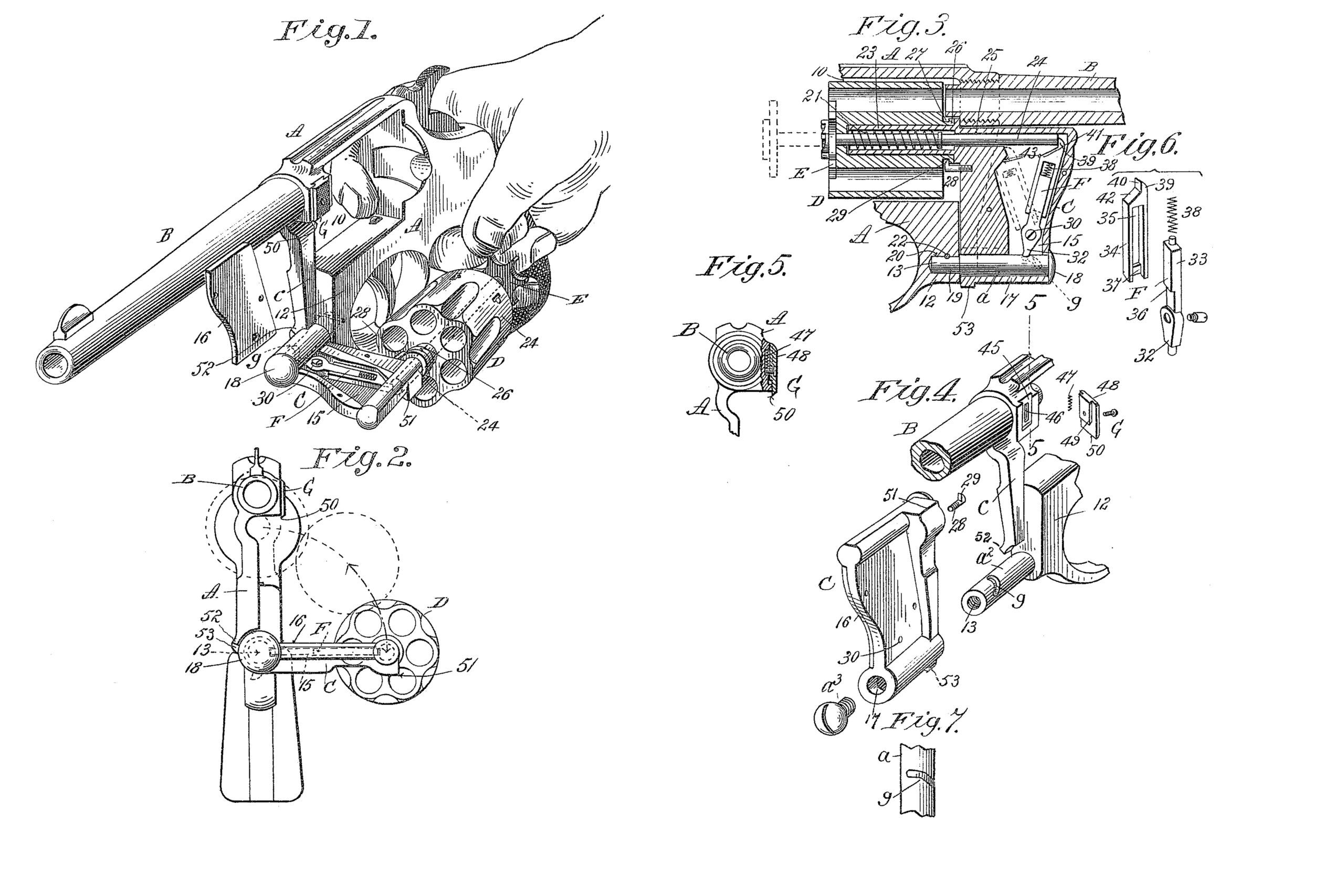
Figure 1 is a perspective view of a revolver, showing the cylinder-yoke as swung downwardly and outwardly for the purpose of actuating the ejector, it being understood that the extent of the swinging movement of the yoke is not quite the maximum, and in this view the plate for covering the recessed part of the yoke in which the ejector-actuating mechanism is contained is shown as displaced for the purpose of clearer illustration. Fig. 2 is a front end view of the revolver, the yoke and cylinder being shown as swung down,and the original and intermediate positions of the cylinder are indicated by dotted lines. Fig. 3 is a central vertical sectional view through a portion of the frame and the barrel and the part within which the cylinder has space for occupancy and also through the yoke and the ejector-actuating mechanism, parts of the latter being shown in face view. Fig. 4 at is a view of portions of the frame and the yoke detached the one from the other and showing a slightly-different detail of construction of the sleeve-joint or pivotal connection by means of which the yoke articulated to the frame, also showing the yoke-catch and the cylinder-retainer detached from the parts on which they are mounted, but having their positions in the drawing adjacent such parts. Fig. 5 is a cross-sectional view taken vertically through the yoke-catch, the transverse plane of section being indicated by line 5 5 on Fig. 4. Fig. 6 is a perspective representation of the different parts separated, which together partially constitute the ejector-actuating device. Fig. 7 is a plan or face view of a part which is fixed or immovably provided on the frame in which is constructed the cam-slot in which the ejector-actuating lever impinges.
Similar characters of reference indicate corresponding parts in all of the views.
In the drawings, A represents the frame of the firearm, which carries in the forward extension thereof the barrel B.
The frame at the rear of the barrel is constructed with the rectangular aperture 10, which affords the space for occupancy by the cylinder, which is carried by and rotatably mounted on the yoke C, jointed to the frame at the forward end of the portion 12 thereof, 13 indicating the pivotal point or line, and all so as to enable the cylinder D, which is mounted on the yoke, to be swung with the latter to have a position within the frame-aperture 10 for firing or to be swung outwardly and downwardly, as seen in Figs. 1 and 2, to leave the cylinder with its chambers unobstructed, whereby the shells may be ejected, whereby the cylinder may be loaded or reloaded, and whereby the cylinder may be cleaned while on the yoke or removed from the yoke. The yoke comprises a block or plate having therewithin the chamber or recess 15, and provided for which is the covering-plate 16. The position of the yoke or cylinder-carrier is forward of the part 12 of the frame and when in its closed position under the barrel. As shown in Fig. 3, the pivotal joint or connection which the yoke has in relation to the frame is constituted by the comparatively long stud or shaft a, passed through a circular longitudinal horizontal hole 17 in the lower part of the yoke up to its head 18, its inner end being necked down, as shown at 19, and said necked-down portion entering the socket 2O therefor in the forward lower part of the frame 12 and retained by the transverse key-pin 22. The cylinder D is rotatable on the rear longitudinal extension of the yoke, which is shown at 23, this part being constructed tubular for the reception therein of the stem 24 of the ejector or extractor E, which stem projects forwardly through the guide opening or passage 25 in continuation of the here within the said tubular yoke extension 23 and terminates within the aperture or chamber 15 in the yoke, all as clearly shown in Fig. 3. The forward end portion of the cylinder has the concentric hub 26, behind the rear end of which is the annular groove 27.
28 indicates a stud or pin the shank of which is screw-threaded and which at its opposite end is provided with the rigid angle lug 29. This stud is screwed into a tapped socket therefor in the yoke closely under the cylinder-supporting tubular stud 23, said lug engaging in the annular groove 27 of the adjacent part of the cylinder. By forcing the lug-provided part 28 around about one-half turn the cylinder thereby becomes disengaged and may be drawn off from the part 23, on which it is rotatably supported.
The ejector-actuating mechanism will be now described as follows: It comprises the lever F, pivoted at 30 to the yoke within the recess 15 thereof for a swinging movement longitudinally relatively to the yoke, while at the same time it has bodily transverse swinging movements in unison with the yoke. Its portion above its pivot is considerably longer than the portion or short arm below the pivot, and the rounded short arm 32 by its extremity protrudes into the cam groove or slot g, which is formed in the aforementioned stud or part a, on which the yoke is hinge-connected. The lever F has its long arm constituted by the portion 33, which is integral with the short arm and which is rendered distensible and contractible by the section 34, which is telescopically combined with the part 33. The part 34 is constructed with the longitudinal aperture 35, which by the opposite walls thereof fits the corresponding edges of said part 33, which latter has the shoulder 36, with which the cross-stop 37 of the part 34 may have a limiting-abutment when said part is distended to the limit of its upward movement by the spring 38. The telescopic section 34 of the distensible lever F has its upper extremity constituted by the engagement member or pawl 39, having the abrupt rearward face and the inclined forward face, and below the said abrupt rearward face, which is indicated by 40, the adjacent part 42 is downwardly and rearwardly beveled, forming a blunt or obtuse nose at its intersection with the longitudinal edge of the distensible part 34. The rearward upper portion of the boundary or wall of the recess 15 in the yoke is formed with the incline or cam surface 43.
The operation of the mechanism last described will be now explained. Assuming that the yoke and cylinder are in their usual positions, the yoke being limited in its closing movement by sidewise abutment against the part c of the frame, if now the yoke is swung outwardly and downwardly the cooperative action between the cam-groove and the lever F will be such that after the lever has proceeded in its bodily swinging movement sidewise for a suitable distance, so that the cylinder is clear from the frame, the lever will have in addition to its bodily swinging movement also an independent movement in a plane angular to the bodily swinging movement, and it will thereby force the ejector to the position indicated by the dotted lines in Fig. 3, whereby the shells or cartridges will be withdrawn from the cylinder chambers. It will be explained in connection with Fig. 7 of the drawings that the grade of the cam-groove in the portion thereof through which the part of the lever F has its initial movement is at most very little, if any, so that the cylinder may reach the intermediate positions indicated by the dotted lines in Fig. 2 before the ejector extracts the cartridges. This is important, for the reason that if the shells or cartridges were crowded outwardly from the chambers immediately the outward movement of the cylinder commenced they would be forced against the breech portion of the frame and the action would be cramped or defeated. Therefore after the cylinder has reached the intermediate position indicated in Fig. 2, which, for instance, may be approximately one-half of its entire movement, the extremity of the lever is then impinged against by the cam groove side, which is decidedly angular to the plane of the swinging movement, so that in the latter half of the throw of the cylinder the ejector-actuating mechanism will be positively and somewhat rapidly operated. The swinging motion of the distensible ejector-operating lever F is such that the same is carried clear to the rearward boundary of the recess 15 in the yoke, the nose 41 following the course of the arrow shown in Fig. 3, and after the said nose has come to contact against the inclined cam-surface 43 the final effect of the forcing action of the side of the cam-groove g against the lever is to crowd the part 3t downwardly relatively to the part 33 against the spring, so that the pawl member 39 disengages the ejector-stem, leaving the latter then free to be retracted by the ejector-spring 21.
to return the cylinder to its place with one of its chambers in alinement with the barrel the telescoping part 34 will click by the end portion of the ejector-stem to take a new engagement therewith.
Fig. 4 illustrates a slightly-different specific joint construction between the yoke and the part of the frame on which it is pivotally connected. In this construction the portion 12 of the frame is constructed with the stud a longitudinally and forwardly extending, the same being integrally made with the frame or rigidly united thereto in any way which is deemed desirable. In this part a the cam-groove g is formed. The lower portion of the yoke is formed tubular to be slipped over the stud a whereby to make a sleeve-joint, and the parts are retained in their appropriate relations by a headed screw a the threaded shank of which enters the screw-tapped socket in the end of the stud. The aperture or chamber within the yoke, which is made substantially the same as the one 15 in the yoke shown in the other construction, Fig. 3, opens through to the bore in the tubular lower part of the yoke, whereby the lower extremity of the lever unobstructedly extends to its operative engagement in the cam-groove g.
In the revolving firearm here illustrated I have shown the provision of a catch G for locking the yoke closely to the frame and for insuring that the chambers of the cylinder carried by the yoke may be more certainly brought to and maintained in alinement with the bore of the barrel than usual heretofore, this result being by reason of the fact that the yoke is locked to the frame at a point in advance instead of to the rear of the cylinder. Heretofore in this type of revolvers the locking has usually been accomplished by the provision of a locking-pin centrally located within the ejector-stem and having applied thereto a spring for forcing it rearwardly, so that its rear end will enter a socket in the portion of the frame next to the rear of the center of the cylinder, accessible catch-operating means being provided, and the action of the leverage between the locking-point at the rear of the cylinder in the forward end of the cylinder and yoke has a considerable tendency to throw the cylinder chambers slightly out of alinement with the bore of the barrel. Therefore in my improved firearm the cheek or portion of the frame in advance of the cylinder-aperture 10 has at its side the vertical dovetailed way 45, within the base seat of which is the further depression l6. The yoke-catch (represented at 50)consists of a block having the dovetailed rib or tongue 49 to fit in the aforesaid way 45, which way is open from the top edge of the said cheek portion of the frame; A spring 47 is located in the aforesaid depression 46, its upper end being in bearing against the upper end wall of said depression, while the lower end of this spring is borne against by the inner end of the screw or stud, which penetrates and is carried as a part of the said block 48, which constitutes the catch, the inner extremity of said screw protruding within the depression 46 to be subject to the compression of the said spring. The catch block is of such length as to normally when forced to its limit by the catch-spring closely overlap the upper outer edge of the yoke G, which is adapted to close in compactly against and under the aforesaid check or portion of the frame and to be securely and firmly so held until the catch is upwardly drawn, which may be done by the thumb and finger of the same hand which grasps the revolver, and while the catch is thus forced to and held in its releasing position a quick jerk of the hand by which the arm is held may be so given as to throw the yoke and cylinder to their outwardly and downwardly swung limit, and when this has been done the ejector will have been operated to throw the shells and then returned to its original position.
As shown in Figs. 2 and i, the lower portion of the frame is made with an abutment 52, and the sleeve-like lower portion of the yoke is constructed with the toe or stop 53, the latter coming into engagement with the abutment after the yoke has been swung sufficiently far down and prevented from an undue swinging motion. The engagement of the one part with the other also insures that the yoke and cylinder may be held with a certain degree of firmness while the loading of the chambers is performed.
Having thus described my invention, what I claim, and desire to secure by Letters Patent, is—
1. In a revolving firearm, the combination with the frame of the arm, provided with a cam-surface, and the yoke movable relative to the frame as described, and carrying the cylinder and an ejector, of a pivotally-mounted ejector-actuating device, bodily movable in unison with the yoke, and also independently movable by its impingement against said cam-surface for projecting the ejector, and means for returning the ejector-actuating device to its normal position.
2. In a revolving firearm, the combination with the frame, having the cam-groove g, and the yoke carrying the cylinder which is provided with the ejector, of a lever intermediately pivoted to a part of the yoke and adapted to be moved bodily in unison therewith, having one member thereof engaging the ejector, and having the other member thereof in impingement against the surface of the cam-groove, and so arranged that as the lever is bodily moved when the yoke is swung, it will also have the additional swinging and ejector-operating movement, for the purpose set forth.
3. In a revolving firearm, the frame, having the aperture 10, and the cam-groove g, the yoke, with the cylinder and ejector, mounted to swing on said frame, the said yoke having pivoted thereon the two-armed lever F, one member being provided with a yielding pawl, and the other extending to engage within said cam-groove, substantially as and for the purposes set forth.
4. In a revolving firearm, of the character described, the frame having the cylinder-carrying yoke mounted for a swinging movement thereon, and the yoke-carried cylinder provided with an ejector, and spring-retracted ejector-rod, forwardly extending, a lever F pivotally mounted on the yoke in advance of the forward end of the ejector-stem and having a yielding pawl in engagement with said ejector-stem and a cam with which the lever, as it swings in unison with the yoke, engages, so that as the yoke is outwardly and downwardly swung, the lever will rearwardly force the ejector-stem and be finally moved out of engagement therewith, leaving the said stein then free to be rearwardly returned to its original position, the yielding pawl end of the said lever permitting said lever to be returned to resume its engagement at the forward end of the ejector-stem, substantially as described.
5. The combination with the frame, of the firearm, having the cylinder-carrying yoke mounted for a swinging movement thereon, and provided with a part in which is a groove, a portion of which is substantially coincident with the plane of swinging movement of the yoke, while another portion thereof is decidedly angular to such plane of movement, the ejector, and a lever pivotally mounted on the yoke having one member adapted to engage and to operate the ejector, and having its other member in impingement in said groove, and all arranged whereby the ejectoractuating swinging movement of the said lever transpires after the yoke has been swung clear of the frame, substantially as described.
6. In a revolving firearm, the combination with the frame of the arm having a part thereof constructed with the cam-surface, and the yoke mounted to swing on the frame as described, and carrying the cylinder and an ejector, of a pivotally-mounted ejector-actuating lever, bodily movable in unison with the yoke, and also independently movable by its impingement, as it moves, on said cam-surface, for projecting the ejector, and a cam surface in contact with which the lever is brought after it has projected the ejector for displacing the engaging part of the lever from the ejector.
7. In a revolving firearm, the combination with the frame of the arm having a part thereof constructed with the cam-surface, and the yoke mounted to swing on the frame as described, constructed with a cam-surface 43 and carrying the cylinder and an ejector, of a pivotally-mounted ejector-actuating lever bodily movable in unison with the yoke, and also independently movable by reason of its impingement on said first-named cam-surface, and having a spring-distended and yielding ejector-engaging member or pawl, and all so arranged that after the lever has projected the ejector it will by contact on said cam 43, insure the contraction of the said lever for its disengagement with the ejector.
8. In a revolving firearm, in combination, the frame having the fixed round extension provided with the cam-groove g, the yoke hung thereon for a sidewise swinging movement which has the recess 15 and the tubular ejector-support 23, the passage therein extending longitudinally into communication with said recess, the cylinder and the ejector having its stem playing through the tubular cylinder-support and extending into said recess, the lever F having the long arm thereof 20 formed by the two members 33 and 34, the latter of which is telescopically engaged about the other, and is adapted by its extremity to engage the ejector-operating stem, and having the distending-spring, substantially as described.
9. In a revolving firearm, in combination, the frame having the fixed round extension provided with the cam groove g, the yoke hung thereon for a sidewise swinging movement-having the recess 15, with the cam-surface 43 therein, and provided with the tubular ejector-support 23, the passage therein extending longitudinally into communication with said recess, the cylinder and the ejector having its stem playing through the tubular cylinder-support and extending into said recess, the lever F having the long arm thereof formed by the two members 33 and 34, the latter of which is telescopically engaged about the other, and is adapted by its extremity to engage the ejector-operating stem, and having the nose 41 and the distending-spring, and the covering-plate 16 for said recessed yoke, substantially as described.
10. In a revolving firearm, the combination with the yoke mounted for the sidewise swinging movement on the frame of the arm, and having the cylinder, rotatably mounted there on, which is provided with the concentric end hub 36 having the annular groove 27, of the stud or pin rotatably supported by, and projecting beyond the face of the yoke adjacent said grooved-hub-provided part of the cylinder, and having the rigid angular member engaged in said groove, and adapted on the turning of the stud to be disengaged there from, to permit the removal of the cylinder.
Signed by me at Springfield, Massachusetts, in presence of two subscribing witnesses.
GEORGE A. OWEN.
Witnesses:
WM. S. BELLOWS,
M. A. CAMPBELL.