
US 685880
UNITED STATES PATENT OFFICE.
AUDLEY H. STOW, OF MATEWAN, VEST VIRGINIA.
REVOLVING FIREARM.
SPECIFICATION forming part of Letters Patent No. 685,880, dated November 5, 1901.
Application filed March 27, 1899. Serial No. 710,709. (No model)
To all whom it may concern:
Be it known that I, AUDLEY H. STOW, a citizen of the United States, residing at Matewan, in the county of Mingo and State of West Virginia, have invented a new and useful Improvement in Revolving Firearms, of which the following is a specification.
My invention relates to that class of revolving firearms in which a many-chambered cylinder is made to revolve at the rear of the barrel, particularly revolvers of the breakdown class and the objects of my invention are, first, to provide a firearm which is less liable to be injured by blows or rough usage; second, to provide a firearm in which a spring acting upon a lever by this means depresses the barrel and through the resulting action of the extractor-cam automatically ejects the shells, and, third, to provide at the same time a firearm in which not only the frame may be unlocked, but the shells automatically ejected by a single movement of the thumb or finger of the hand which holds the revolver. I attain these objects by the mechanism illustrated in the accompanying drawings, in which—
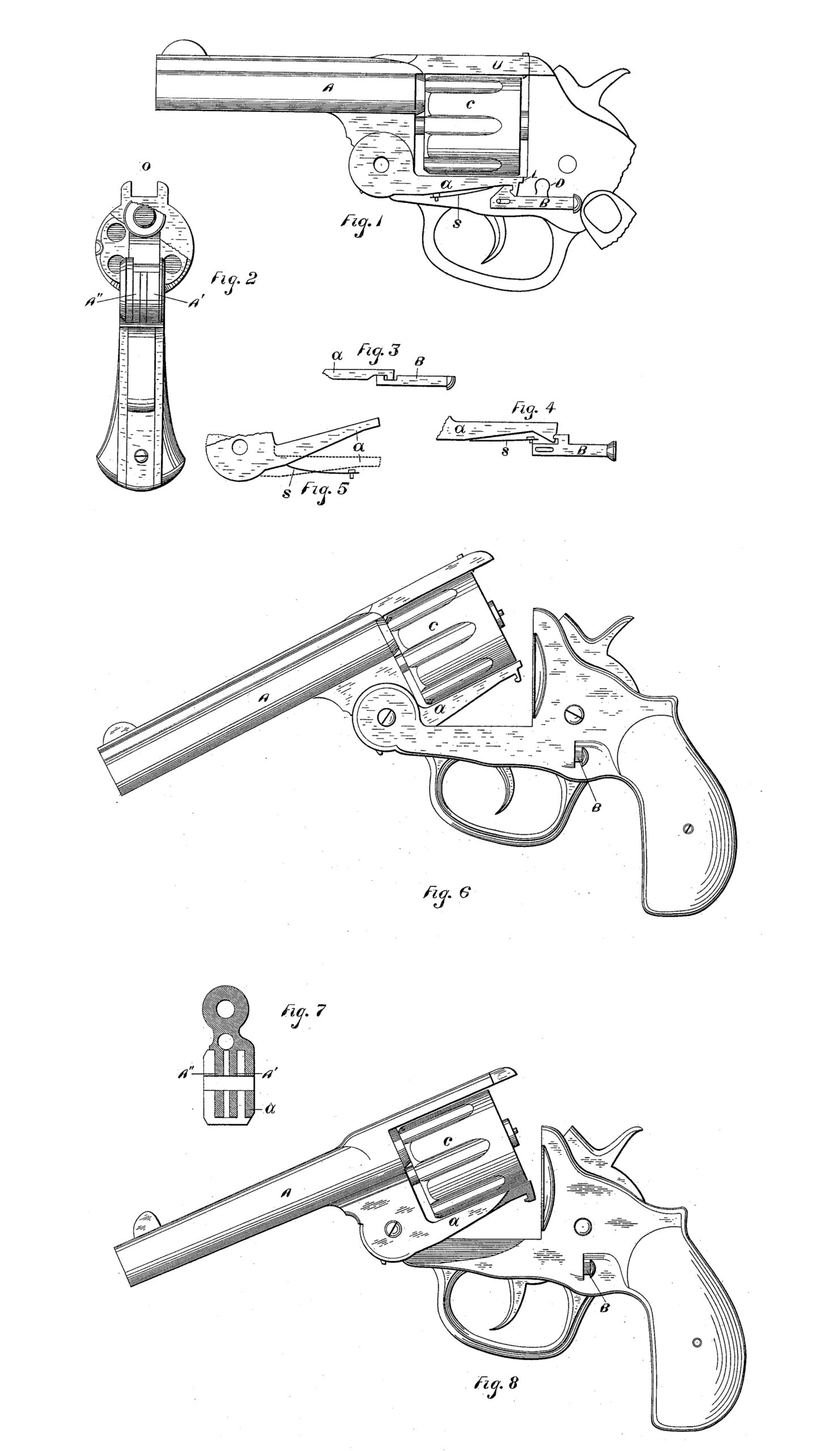
Figure 1 is a full side view of the cylinder and barrel, with a rearward extension of the latter along and underneath the cylinder in the shape of a lever and herein designated as a barrel-lever, a catch and a portion of the revolver-frame in outline being shown; Fig. 2, a broken front view of the revolver locked in position ready for firing; Fig. 3, a view from above of a portion of the barrel-lever with one form of catch; Fig. 4, a side view of another form of barrel-lever and catch; Fig. 5, a broken side view of still another form of barrel-lever; Fig. 6, a full side view of revolver, the barrel being depressed, and thus exposing the barrel-lever; Fig. 7, a vertical cross-section along the axis of the joint-pivot; Fig. 8, a full side view of revolver, the barrel-lever being on the outside of the usual joint.
In revolvers of the breakdown class the strap U, Fig. 1, is formed by the rearward extension of the barrel A, the barrel being also extended downward at its rear end in such a manner and to the end that the barrel and cylinder may be pivotally connected with the revolver-frame, the cylinder being the held in its proper position or relation to the barrel by the center-pin, the said lower part of the barrel forming the usual slotted joint, consisting of the two downward extensions A’ and A”, Fig. 2, and holding the idler or extractor cam. My invention consists in a rearward extension of the barrel along and underneath or on the lower side of the cylinder, the said extension taking the form usually of a lever or levers and herein designated as a “barrel” lever or levers, as a, Figs. 1, 3, 4, &c., a suitable catch B holding or releasing the said barrel-lever at will. A suitable barrel-lever spring S, Figs. 1, 4, and 5, may serve to throw the barrel-lever up quickly when released by the thumb-catch 13, thus depressing the barrel and ejecting the shells through the resulting action of the extractor-cam. The said barrel lever or levers may be of a form, as a, Figs. 1, 3, and 4, adapted to engage with some simple thumb or finger catch that may be operated by the thumb or finger of the hand that holds the revolver, or the said barrel-lever may be constructed solely with a view to giving strength, as a in Fig. 5, or the said barrel-lever may be constructed with a view alone to furnishing a bearing for the said barrel-lever may be formed by the rearward extension of either of the sides A’ or A”, Fig. 2, of the slotted joint which holds the idler or extractor-cam, or both sides of the slotted joint may be extended rearwardly either as separate barrel-levers or as a common barrel-lever, which may take the form of two separate barrel-levers suitably united so as to form a common barrel-lever. The barrel-levers may be of the same form or different, as one to give strength and one to operate the locking device. Where the said barrel-lever is formed by the rearward extension of the slotted joint it may be called an “inside” barrel-lever, as it will lie within the forward portion of the revolver-frame, that underlying the cylinder when the revolver is locked ready for firing. Fig. 6 shows a breakdown revolver with in side barrel-lever, but with a “Colts” frame. When the revolver is ready for firing, the barrel-lever will evidently lie within the revolver frame. The barrel lever or levers, however, instead of being so placed as to lie within the revolver-frame may be so placed as to lie on the outside of and by the side of that portion of the revolver-frame underlying the barrel when in position for firing. The barrel-lever may in the latter case be called an “outside” barrel-lever. Fig. 8 shows a breakdown revolver with outside barrel-lever.
Where the barrel-lever is so constructed and placed as to lie by the side of the revolver-frame, the barrel lever being also adapted to engage with a thumb or finger catch, a suitable recess containing said catch is provided for the rear end of the lever, as shown in Fig. 8. As is also shown in Fig. 8, this recess is preferably extended forwardly in the shape of a shoulder or ledge underlying the lever and intended to protect it, as from blows from below.
Outside barrel-levers may lie either to the right or to the left of the forward portion of the revolver-frame, or two outside barrel-levers may be used in the same revolver, one to the right and one to the left, which may be of the same form or different, as one to give strength and one to operate the locking device. As in the case of the inside barrel-levers, the outside barrel-levers may also be suitably united, so as to form a common barrel-lever.
Various combinations of barrel-levers, as one on either side of the revolver-frame and one within the frame, may be used, although whether the number be one, two, or more they act conjointly and may be described as a single barrel-lever made up of several component parts or pieces acting as a whole or unit. The barrel-lever on the outside of the revolver-frame has the especial advantage of not interfering with the firing and revolving mechanism. It is-also well adapted to give strength, in that in striking an opponent with the revolver the blow on the barrel will be transmitted to the frame instead of tending, as heretofore, to derange the alinement of the cylinder and-strap with the said barrel and may be readily adapted to engage with the said thumb or finger catch. The inside barrel-lever, however, is especially adapted to furnish a bearing for the spring by means of which the barrel is automatically depressed, may incidentally add considerable strength, and has also the special advantage of being concealed within the revolver-frame, except when the barrel is depressed.
The form of the barrel lever or levers, whether inside or outside barrel-levers, may be varied largely—as, for example, the inside barrel-lever, in order to avoid interfering with the revolving and firing mechanism,may be bent out and around the firing and revolving mechanism, or the inside barrel-lever may be flattened very much at the rear end, so as to overlie, and thus avoid interfering with, the firing and revolving mechanism. The length also of the barrel lever or levers may be varied largely. As an extreme the barrel-lever may be shortened until it not only avoids interfering with the firing and revolving mechanism, but until it barely furnishes bearing for the said barrel-lever spring.
The barrel lever or levers, whether inside or outside barrel-levers, or both, are preferably forged in one piece with the barrel, as shown in Figs. 1, 6, and 8, although one or more may be separate parts suitably attached to the barrel and to each other, as may be desirable.
The thumb or finger catch is preferably so constructed and placed in the frame of the revolver that it may be conveniently operated by the thumb or finger of the hand that holds the revolver, or where more than one barrel-lever is used a corresponding number of catches may be used. Three different forms of catches are shown in Figs. 1, 3, and 4. In order to release the barrel-lever a, Fig. 1, the catch B is pushed forward by the thumb or finger, when the two corresponding teeth, the one in the catch and the one in the barrel-lever, become disengaged, which leaves the barrel-lever spring S free to throw or push the barrel-lever up quickly. The two teeth or shoulders shown in Fig. 3 are intended to engage horizontally, as it were, instead of vertically, as in Fig. 1. In order to release the barrel-lever, the catch B, Fig. 4, is pushed or pulled backward. The form of catch may be varied largely as the best practice may require and may be pushed or pulled forward or backward or inward in such a manner and direction as its construction may make necessary. Where no form of catch is used in conjunction with the barrel-lever, as where the barrel-lever is intended merely to give strength or to serve as a bearing for the barrel-lever spring, or both, some form of catch may be used in connection with the strap as at present. Where the said thumb or finger catch is used in connection with the barrel-lever, the catch at present used with the strap may be omitted, the rear portion of the strap simply resting in a slot or recess formed by upward projections O, Fig. 2, of the revolver-frame and somewhat similar to the usual catch-posts.
In view of the differences shown or suggested and others which may obviously be made it is to be herein understood that I do not limit myself to the exact construction shown or described, but hold myself at liberty to make such changes and alterations as fairly fall within the spirit and scope of my invention.
Having thus described my invention, what I claim as new, and desire to secure by Letters Patent, is—
1. In revolving firearms, particularly of the breakdown class, the combination, substantially as aforesaid, of the barrel, and the rearward extension of the said barrel, along and underneath the cylinder, designated as the “barrel-lever,” together with a suitable recess in the revolver-frame adapted to receive the said barrel-lever, when the revolver is closed, whereby blows on the barrel may be transmitted to the frame, instead of as heretofore, tending to derange the alinement of the cylinder and strap, with the barrel.
2. In revolving firearms, particularly of the breakdown class, the combination, substantially as aforesaid, of the barrel, the rearward extension of the barrel along and underneath the cylinder, designated as the “barrel-lever,” together with a suitable recess in the revolver-frame, adapted to receive the said barrel-lever, when the revolver is closed, and the barrel-lever catch, also within the revolver-frame, adapted to engage or release at will the said barrel-lever, whereby blows on the barrel will be transmitted to the frame, without injury to the integrally-attached portions of the barrel, while the said barrel-lever may be released at will by the revolver-hand alone.
3. In revolving firearms, particularly of the breakdown class, the combination, substantially as hereinbefore set forth, of the barrel, the rearward extension of the barrel along and underneath the cylinder, designated as the “barrel-lever,” together with a suitable recess in the revolver-frame, adapted to receive the said barrel-lever, the barrel-lever catch also within the revolver-frame and adapted to engage or release at will the said barrel lever, and the barrel-lever spring within the revolver-frame in a suitable position to act upon the said barrel-lever; all of which where by blows on the barrel may be transmitted to the frame, the said barrel-lever may be released at will, and when so released, the barrel may be automatically depressed through the resulting action of the said barrel-lever spring upon the said barrel-lever, all substantially as set forth.
AUDLEY H. STOW.
Witnesses:
R. J. WATTS,
T. D. BURGESS.