
US 654850
UNITED STATES PATENT OFFICE.
FREDRICK SHIELDS, OF ERIE, PENNSYLVANIA.
REVOLVING PISTOL.
SPECIFICATION forming part of Letters Patent No. 654,850, dated July 31, 1900.
Application filed January 26, 1900. Serial No. 2,847. (No model.)
To all whom it may concern:
Be it known that I, FREDRICK SHIELDS, a citizen of the United States, residing at Erie, in the county of Erie and State of Pennsylvania, have invented certain new and useful Improvements in Revolving Pistols; and I do hereby declare the following to be a full, clear, and exact description of the invention, such as will enable others skilled in the art to which it appertains to make and use the same, reference being had to the accompanying drawings, and to the letters of reference marked thereon, forming part of this specification.
My invention relates to improvements in revolving pistols; and it consists substantially in so constructing the hammer and trigger mechanism thereof that the pulling back of the trigger turns the cylinder and throws the hammer back, where it is retained by the trigger mechanism until the trigger is moved slightly forward, which movement releases the hammer.
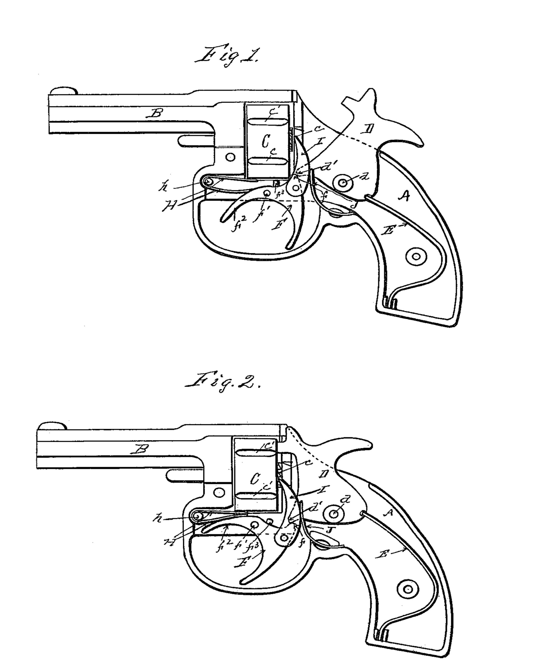
The object of this invention is to construct the revolver so that while it is operated by the trigger mechanism to rotate the cylinder and cook the hammer, as is ordinarily the case with what are known as “self-cocking revolvers,” a slight forward movement of the trigger is necessary to discharge it. The mechanism which I have devised for this purpose is hereinafter fully set forth and described and illustrated in the accompanying drawings, in which Figure 1 is a side view in elevation of a revolver embodying my invention with the hammer raised and one half of the frame removed, so as to show the internal mechanism thereof. Fig. 2 is a like view of the same with the hammer down.
In the drawings thus illustrating my invention, A is the frame of the revolver, B the barrel, and C the cylinder, all of the usual and ordinary construction. The hammer D is driven by a spring E, secured in the frame A in the usual manner. The pivot d, upon which the hammer D is mounted, is near the bottom thereof, and the hammer is provided with a toe d’, which extends forward from the pivot d. The trigger F is pivoted in a slot in the frame under the cylinder C and is provided with a backwardly-extending projection f, adapted to engage the toe d’ on the hammer on the trigger.
D, as shown in Fig. 2, so that when the trigger F is pulled backward the projection f thereon forces the toe d of the hammer upward until it passes considerably above a line drawn from the trigger-pivot f and the hammer-pivot d, as illustrated in Fig. 1, in which position the toe d’ of the hammer D contacts with the portion f of the trigger F, so as to rest thereon and be supported thereby, the angle of contact being such that the parts remain firmly locked in this position until the trigger F is swung on its pivot slightly forward, which serves to move the portion f of the trigger back sufficiently to unlock it from the toe d’ of the hammer and allow the hammer actuated by the spring E to fall.
For the purpose of moving the trigger F forward to release the hammer D, I provide an arm f2 on the trigger which extends forward from the trigger-pivot f’, so that when the hammer is raised, as illustrated in Fig.1, this arm f2 is just in front of the trigger-finger, so that a slight forward pressure thereon releases the trigger F, so that the hammer D falls into the position illustrated in Fig. 2.
The trigger-spring H is simply a flat U-shaped spring secured by a stud h in the frame, one end of the spring contacting with the under side of the cylinder C and the other with the arm f2 of the trigger F, so that this spring H operates both on the cylinder and on the trigger. For rotating the cylinder C there are ratchet-teeth c on the rear end thereof of the usual type, and on the trigger there is pivoted a dog I, which is held in place by a spring J, so that each time the trigger F is pulled backward the dog I engages one of the teeth of the ratchet c and rotates the cylinder the proper distance, when a lug f on the trigger F engages one of the slots c’ in the periphery of the cylinder C and retains it in proper position until the pistol is discharged.
Having thus fully described my invention so as to enable others to make and use the same, what I claim as new, and desire to secure by Letters Patent of the United States, is—
1. The combination in a pistol, of a spring-actuated hammer pivoted in the pistol-frame, a forwardly-projecting toe on the hammer, and a trigger pivoted in the pistol-frame in front of the axis of the hammer having a rearward projection thereon adapted to directly engage the toe of the hammer and adapted to cock and release the hammer by the movement of the trigger, substantially as and for the purpose set forth.
2. The combination in a pistol, of a revolving cylinder, a spring-actuated hammer pivoted in the frame of the pistol, a forwardly projecting toe on the hammer, a trigger pivoted in the pistol-frame in front of the hammer and under the cylinder, a projection on the trigger extending rearwardly from the pivot thereof and adapted to directly engage the toe on the hammer and adapted to cook and release the hammer by the movement of the trigger, and a spring-actuated dog adapted to engage a ratchet on the cylinder and rotate it when the trigger is drawn back, substantially as and for the purpose set forth.
3. A pistol-trigger having a projection to the rearward of the pivot-opening therein, a downwardly-projecting arm adapted to be engaged when pulling the trigger back to cook the hammer, and a forwardly-projecting arm for moving the trigger forward to disengage the trigger from the toe of the hammer, substantially as and for the purpose set forth.
4. The combination in a revolving pistol, of a frame A, a cylinder C, a barrel B, a hammer D pivoted in the frame A and having a forwardly-projecting toe d’ thereon, a spring E engaging the hammer D, a trigger F pivoted in the frame A below the cylinder C, a rearward projection f on said trigger, adapted to engage the toe d’ on the hammer D, an arm f2 projecting forwardly from the trigger-pivot f’, a trigger and cylinder spring H, and a cylinder-rotating dog I, substantially as and for the purpose set forth.
In testimony whereof I my signature in presence of two witnesses.
FREDRICK SHIELDS.
Witnesses:
MATTHEW GRISWOLD, Jr.,
FRED EINFELDT.