
US 655844
UNITED STATES PATENT OFFICE.
JOSEPH H. WESSON, OF SPRINGFIELD, MASSACHUSETTS, ASSIGNOR TO SMITH & WESSON, OF SAME PLACE.
REVOLVER.
Specification forming part of Letters Patent No. 655,844, dated August 14, 1900.
Application filed March 3, 1900 Serial No. 7,220. (No model.)
To all whom may concern:
Be it known that I, JOSEPH H. WESSON, a citizen of the United States of America, residing at Springfield, in the county of Hampden and State of Massachusetts, have invented new and useful Improvements in Revolvers, of which the following is a specification.
This invention relates to self-cocking revolving firearms of the type known as the “solid frame,” in which the cylinder swings out of the frame in a line at-right angles to the barrel; and the invention is directed especially to the improvement of devices-for effecting the rebounding of the hammer, to the improved construction of the cylinder-stop, to an improved construction of a safety-catch for the hammer to prevent an accidental discharge of the arm by a blow on the hammer before the arm is cocked, and to the improvement of various parts co-acting with the above devices, all as fully set forth in the following specification and summarized in the claims forming a part thereof.
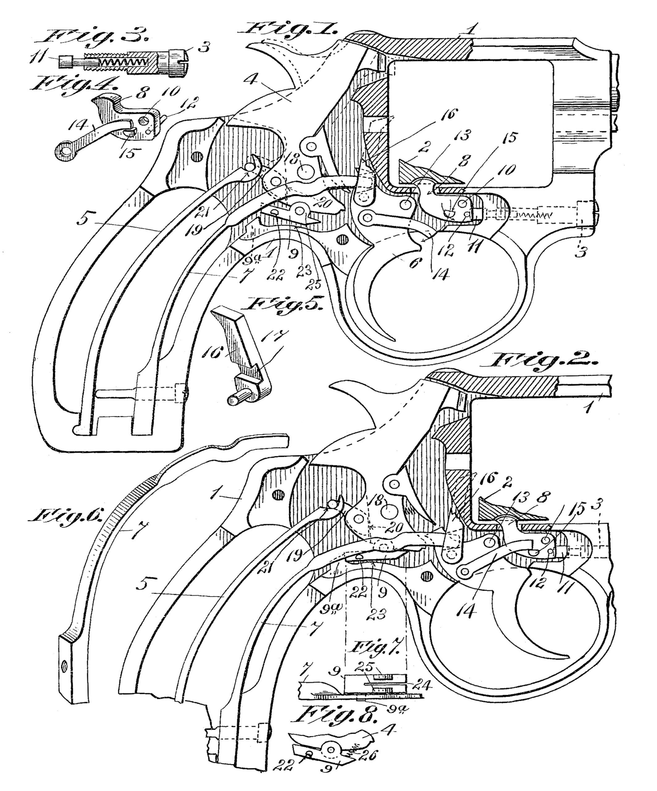
In the drawings forming part of this specification, Figure 1 is a vertical sectional view of a firearm embodying this invention, the barrel being broken off, the position of the parts being that which they occupy immediately after the discharge of the arm and before the trigger has been released. Fig. 2 is a similar view to Fig. 1, showing the position of the parts after the trigger has been released. Fig. 3 is a partly-sectional view of the pin on which the cylinder-yoke swings. Fig. 4 is a perspective view of the cylinder-stop and a spring-lever which actuates it. Fig. 5 is a view in perspective of the hand which rotates the cylinder. Fig. 6 is a perspective view of the spring which operates on the trigger and other parts of the mechanism of the arm. Fig. 7 is a top plan view of the hammer-blocking device and one end of the trigger-spring. Fig. 8 is a side elevation of a part of the lower end of the hammer and an attached part, illustrating a modification of the preferred construction. These drawings are scaled up to about double the size of the firearm.
Referring to the drawings, 1 represents the frame of the firearm. The cylinder is indicated by 2; but only a small portion thereof which receives the cylinder-stop is shown in Figs. 1 and 2. This cylinder is hung on a pin in a yoke which swings at right angles to the barrel, the pivot-pin 3 of said yoke being shown in dotted lines in Fig. 1, partly in Fig. 2, and in full lines and partly in section in Fig. 3. The cylinder-yoke is not shown, but its construction is well known and the illustration thereof not called for herein, as it forms no part of the invention.
The hammer is indicated by 4, the mainspring by 5, the trigger by 6, the trigger spring by 7, the cylinder-stop by 8, and the safety-catch for the hammer by 9.
The normal position of all the parts of the firearm is shown in Fig. 2. In this position the cylinder is in its proper place in the frame 1, one of the chambers thereof being held in axial alinement with the barrel by the engagement of the cylinder-stop 8, as is usual in revolving firearms. This cylinder-stop is pivotally supported, near one end thereof, in the frame at 10, and its opposite upturned end engages one of the grooves cut in the cylinder to receive it and is held in this engaging position by a spring-plunger 11, mounted in the end of the pivot-pin 3 of the cylinder-yoke. Said plunger does not bear directly against the cylinder-stop 8, but bears against a pin12, which is fixed therein below its pivotal point and projects laterally therefrom. The use of this-pin 12 is rendered necessary only because in this construction the yoke-pivot is slightly out of line with the end of the cylinder-stop 8. The trigger 6 is hung in the frame on the pin 13, and fixed on the side of the trigger is the spring-lever 14, which, as the parts are placed in Fig. 2, bears on the short stud 15, which projects from the side of the cylinder-stop. This relation is shown clearly in Fig. 4. This member 14 is termed the “spring-lever” because while its function is entirely that of a lever it must be capable of yielding laterally at a certain point in its movement in order to permit the end thereof to snap over the stud 15. Its operation is as follows: With the parts in the position shown in Fig. 2 if pressure be applied on the trigger by the finger it will by its swinging movement cause the spring-lever 14, which bears on the stud 15, to swing the cylinder-stop 8 downward and effect its disengagement from the cylinder 2. It then slides off from said stud because of the swinging of the trigger and stop in opposite directions. When the trigger is released, its spring 7 will cause it to swing back to the position shown in Fig. 2, and meanwhile the cylinder-stop will have swung back and entered another groove or notch in the cylinder, which in the meantime has been rotated by the hand 16. Now as the trigger moves back to normal position the end of its spring-lever 14 will strike against the under side of the stud 15, which is beveled, as shown in Fig. 4, and said lever will thereby be cammed out laterally over the end of the said stud and snap into its proper position over it ready for the next operative movement of the trigger. When said lever 14 swings the cylinder-stop out of engagement with the cylinder, it compresses the spring-plunger 11, which yieldingly holds the stop in the path of the stop-notches on the cylinder and in position to snap into one of them when it arrives in registering position with said stop. The intermittently-rotative movements of the cylinder are imparted to it by said hand 16, which is pivotally hung on one side of the trigger 6 and is shown in perspective in Fig. 5. In the side of the hand next to the trigger and extending transversely thereacross is a groove 17, inclined to the lengthwise dimension of said hand in the direction of the cylinder 2. The extreme end of the spring 7 rests in this groove and bears down on the upwardly-inclined bottom edge thereof at a point beyond a vertical central line drawn through the pivot of said hand, and hence said spring will force the upper end of said hand yieldingly against the ratchet on the cylinder, (not shown,) whereby the intermittent vertical movements of the hand will cause the rotation of said cylinder in the usual manner. The movement of the trigger rearwardly effects the cooking of the hammer in the usual manner by the engagement of the upper end of the trigger with the lower end of the cocking-lever 4a, pivotally hung on the forward edge of the hammer in the manner usual in firearms of this class. The spring 7, bearing on the hand, as stated, also serves as the trigger-spring through the connection of the hand with said trigger, as stated, and still another function of said spring is to depress the end of the safety-catch 9 on the hammer and cause its engagement with a projection 9a on the frame of the firearm, whereby after the rebound of the hammer to the position shown in Fig. 2 it cannot be forced forward into contact with the cartridge by a blow.
The hammer 4 is pivotally supported in the frame on the pin 18 and is connected with its spring 5 through the stirrup 19. The latter is hung in a vertical slot in the rearwardly projecting bottom part of said hammer, the depth of which slot is indicated by the dotted line 20, and that side of the stirrup lying next to said slot is made parallel with said bottom part of the latter, and only a little play is permitted to said stirrup on its pivot owing to the proximity of said parallel parts of the stirrup and slot part of said stirrup which bears against the bottom of said slot terminates at a point located substantially between the pivotal point of the stirrup and that of the hammer, and from thence the stirrup trends backward toward the end thereof which is engaged by the end of the spring 5 in the manner usual in firearms of this class. It follows from this arrangement of the stirrup and hammer that in a state of rest the hammer will occupy the position shown in full lines in Figs. 1 and 2. When the arm is cocked, however, and the hammer then released, as in the act of firing, the impetus given to the hammer by its spring will carry it past the stated normal position of rest into contact with a cartridge, which The upper end of said flat position is indicated in dotted lines in Fig. 1. It will be seen in this view that as the hammer throws beyond its position of rest the end of the stirrup in engagement with the spring 5 moves up on the latter away from its seat 21 thereon, and because of the nature of the connection between the stirrup and hammer the end of the stirrup in the spring will be thrown upward and forward against the end of the latter which projects beyond the seat of the stirrup, thus putting the spring under a slight tension, as compared with its position of rest, which is sufficient to cause the hammer to rebound from the dotted-line position to the full-line position shown in said Fig. 1. This rebounding action of the hammer takes place before the pressure of the finger is taken from the trigger, and the parts are therefore in the position shown in Fig. 1, in which the trigger-spring is under tension by reason of this position of the trigger. Upon the release of the trigger its spring 7 will carry it to the position shown in Fig. 2, and the end of the spring will swing downward and assume the position in which it is shown in said figure. During its said downward movement said spring will strike the pin 22, which projects from the side of the safety-catch 9, pivotally hung on the lower end of the hammer, this position of engagement between the spring and said catch being shown in Fig. 7. The impact of the spring on said pin, which is located near one end of the catch, will cause the latter to be swung downward and bring its rear end opposite the projection 9a on the frame, and thus render it impossible to move the hammer forward from its position of rest.
In Fig. 6 is shown a perspective view of the spring 7. It will be observed that the forward end thereof, which bears on the pin 22 and engages the trigger and hand, is turned up edgewise. This is for the purpose of adapting it to its location alongside of the hammer without unduly widening the frame.
During the cocking movement of the hammer the end of the catch 9 lying next to the boss 9a will be drawn forward over the part 23 of the frame which lies in the path of its movement and will thus be forced upward to the position shown in Fig. 1, to the end that when the hammer descends said catch may clear said projection. To adapt the said catch to remain set in any position to which it may be moved around its pivot, the body part thereof is slotted, as indicated by 24, from one end thereof to a point extending beyond the upstanding lugs 25, by which it is pivotally supported on said hammer, and that portion of the hammer embraced between said lugs 25 is made somewhat thicker than the space between the latter. Thus when the catch is placed in its proper position the said lugs are opened slightly and sprung over that part of the hammer on which it is pivoted, and sufficient frictional resistance is thus provided between the catch and its support to insure it from moving thereon by its own weight or from any sudden jar or blow the arm may be subjected to. Without this or some similar provision for preventing the catch 9 from swinging on its pivot without restraint it would come in contact with the projection 9a of the frame during the descent of the hammer, and thus prevent the latter from reaching the cartridge.
In Fig. 8 is shown means for holding the end of the catch 9 up in contact with the ed go of the hammer after the latter has been cocked, and it consists in locating a spring 26 between the end of the catch and the edge of the hammer in such position that the opposite end thereof, which engages with the frame, will be pressed upward. This construction is an alternative of the slit 24 in the catch, which has been described.
Having thus described my invention, what I claim, and desire to secure by Letters Patent of the United States, is—
1. In a revolver, a frame, cylinder, a hammer, a trigger, a hammer-spring, a safety-catch on the hammer, a trigger-spring, and a shoulder on the frame, said trigger-spring being adapted, upon the release of the trigger, to engage said catch and move it into connection with said shoulder on the frame, whereby the movement of said hammer toward the head of a cartridge will be blocked, and means for releasing said catch by the cocking movement of the hammer, substantially as described.
2. In a revolver, a frame, a cylinder, a hammer, a trigger, a hammer-spring, a trigger spring, a hand on said trigger adapted to rotate the cylinder by the movements of the trigger, and a safety-catch on the hammer, said trigger-spring being adapted to bear on said hand to hold it yieldingly in cylinder-engaging position and adapted also to bear on said safety-catch to prevent the movement of the hammer toward the cylinder, substantially as described.
3. In a self-cocking revolver, a cartridge cylinder, a hammer-and spring therefor, a trigger, a trigger-spring, a cylinder-stop, a spring plunger for holding said stop in engaging position relative to said cylinder, a spring lever on the trigger adapted to engage a projection on said stop during the beginning of the cooking movement of the trigger to effect the release of said cylinder, and adapted to slide over said projection on the return movement of said trigger, substantially as described.
4. In a revolver, a frame, a hammer pivotally hung therein, and a safety-catch for said hammer pivotally supported thereon, said catch being adapted to frictionally engage said hammer at and about the point of its support thereon, whereby it may retain, temporarily, a certain relative position thereto, substantially as described.
5. In a revolver, a frame, a laterally swinging cartridge-cylinder, a pivot-screw on which the latter swings, a cylinder-stop, a spring actuated plunger located in said pivot-screw and adapted to bear against said stop a trigger, a lever thereon adapted to engage a projection on said step to move the latter out of engagement with the cylinder, a hand on said trigger, and a spring common to both said trigger and hand, substantially as described.
JOSEPH H. WESSON.
Witnesses:
WM. H. CHAPIN,
K. I. CLEMONS.