
US 658314
UNITED STATES PATENT OFFICE.
MARTIN BYE, OF WORCESTER, MASSACHUSETTS, ASSIGNOR TO THE HARRINGTON & RICHARDSON ARMS COMPANY, OF SAME PLACE.
SAFETY MECHANISM FOR DOUBLE-ACTION FIREARMS.
SPECIFICATION forming part of Letters Patent No. 658,314, dated September 18, 1900.
Application filed June 27, 1900. Serial No. 21,731. (No Model.)
To whom it may concern:
Be it known that I, MARTIN BYE, a citizen of the United States residing at Worcester, in the State of Massachusetts, have invented new and useful Improvements in Safety Mechanism for Double-Action Firearms, of which the following, together with the accompanying drawings, is a specification sufficiently full, clear, and exact to enable persons skilled in the art to which this invention appertains to make and use the same.
This invention relates to an improvement in that class of safety mechanism for firearms wherein the hammer is provided with a sliding face-piece securely attached thereto, but movable to a contacting or non-contacting position in relation to the firing-pin and rendering the hammer-stroke effective or non-effective, according to the position of the trigger at the time of such stroke. An example of this class is illustrated in Letters Patent No. 649,809, of May 15, 1900, my present invention being an improvement in the structure and organization of the safety and actuating means, having for its object the simplification of the mechanism and processes of its manufacture, and to provide a safety sliding hammer-face that is directly engaged and operated by the hammer-lifter pawl, the engaging detents, lugs, or surfaces being portions of said slide and lifter, acting upon each ether by immediate contact or without any intervening separable member or members, as more fully hereinafter explained. I attain these objects by the mechanism shown in the drawings, wherein—
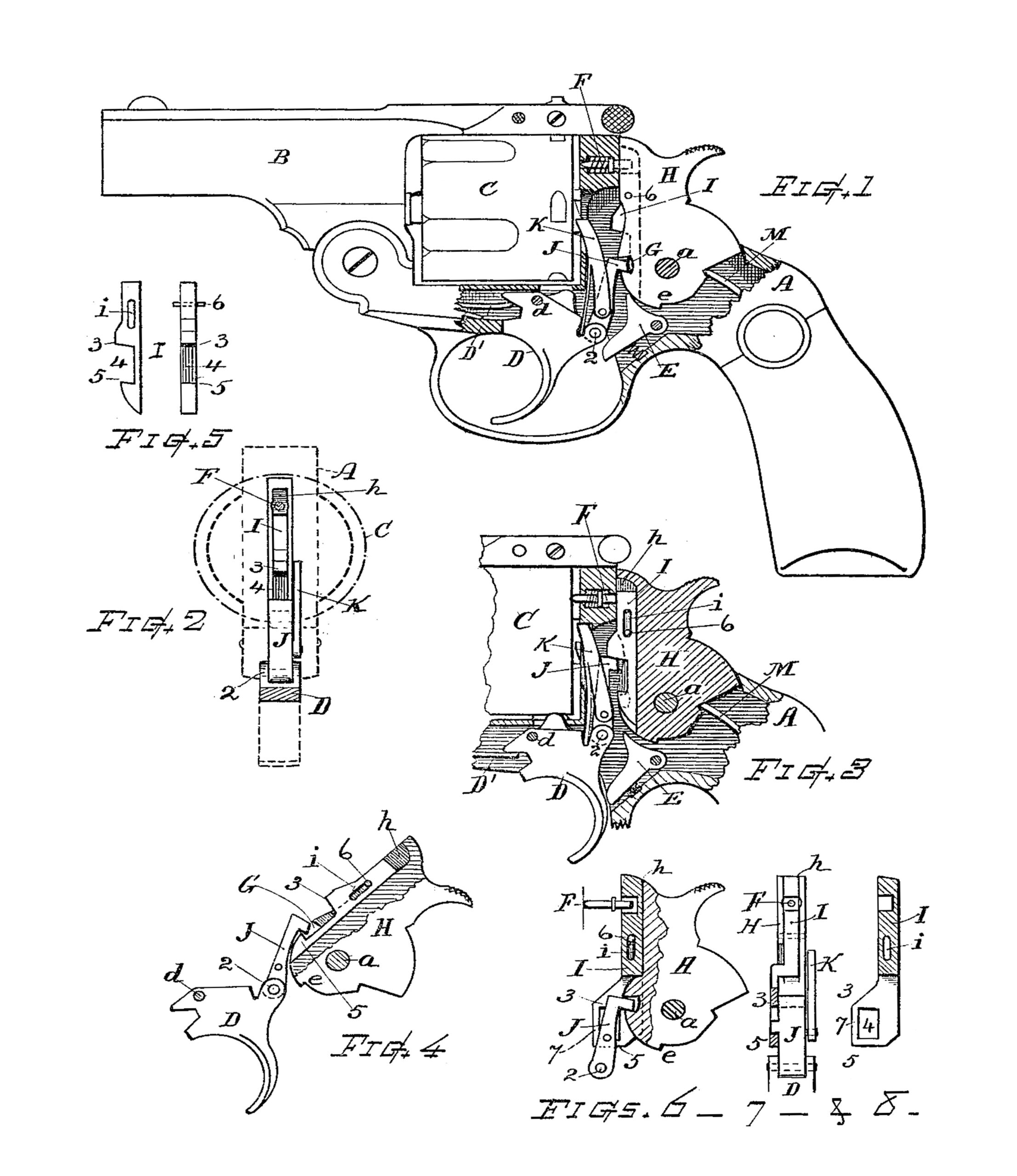
Figure 1 is a side view of a double-action revolver embodying my invention, the side of the frame being broken away to reveal the leak devices. Fig. 2 is a sectional view showing the front of the hammer, the lifter-pawl, &c., with dotted. lines indicating the relative positions of the frame and cylinder. Fig. 3 5 is a vertical sectional view illustrating the positions of the parts at the instant of discharge. Fig. 4 illustrates the manner in which the lifter retains the hammer-face at the position of safety. Fig. 5 shows side and front detail views of the sliding hammerface separate from other parts; and Figs. 6, 7, and 8, illustrate modifications in the form of the safety parts.
In practice my invention is applicable to a revolver or double-action firearm, which in its general construction may be of well-known form and character, as shown in the drawings.
A indicates the frame; B, the barrel; C, the cylinder D, the trigger pivoted at d for swinging action; E, the pivoted sear, and F the firing-pin.
H indicates the hammer pivoted at a and having the usual lifter-engaging recess G and sear-notch e, and J designates the lifter or pawl hinged to the head of the trigger at 2 and having the lug or rearwardly-offset top end, which engages at the recess G for cocking the hammer by pull of the trigger.
K indicates the hand or pawl for turning the cylinder, which pawl may be pivoted in the side of the lifter and M denotes the mainspring, which actuates the hammer-in the manner heretofore practiced.
The part marked I represents the safety member or sliding; hammer-face, which in accordance with my invention is provided at its front with an upper engaging lug, offset, or shoulder 3 and a lower engaging lug, offset, or shoulder 5, formed directly in or upon the sliding face-piece (see Fig. 5) and having a recess or space 4 between said lugs or shoulders. Said sliding face-piece is also formed with a straight rear edge and a suitable contact-face for impingement on the firing-pin head.
The hammer-body has the groove h formed in its front edge and extending down to the tumbler, and said sliding hammer-face is fitted and secured in said groove to slide up and down therein and in such relation that the aforesaid lugs, offsets, or shoulders 3 and 5 immediately co-act with the end or lug of the lifter-pawl J for operation of the sliding face-piece without any intermediary member or separate coupling part, thereby rendering the operation of the sliding hammer-face direct from and by the lifter, and the construction simple and of the least number of parts.
The sliding member I is provided with a longitudinal slot i and is retained in slidable connection with the hammer-body by a pin 6, inserted transversely through the parts, as illustrated, the slide being otherwise independent and free for control by the lifter.
The lower offset or shoulder 5 corresponds with the bottom of the recess G in the hammer-body, or is so located as to be engaged by the lug or nose on the lifter J when the trigger and said lifter are at normal position, and in the event of the hammer being drawn back (see Figs. 1 and 4) the part I is thereby kept at a position of safety should the hammer fall unintentionally. When the sliding hammer-face is at depressed position, the front of the hammer presents a space into which the head of the firing-pin is received without effecting contact therewith; but when elevated the hammer-face presents a solid portion that contacts with and forces forward the firing-pin to discharge the cartridge.
When the trigger is pulled back, as for regular discharge, and reaches the point at which the hammer is released, the lug or end of the litter is at such elevation that it impinges I against and beneath the upper lug or shoulder 3 on the sliding hammer-face and as the hammer drops forces said sliding face I into position for contact with the firing pin head, as illustrated in Fig. 3.
Figs. 6, 7, and 8 illustrate a modified form of the sliding member-in which the lower portion is laterally offset, bringing the engaging lugs or shoulders 3 and 5 at one side of the lifter I to be acted upon directly by the projecting lug on the side of said lifter, this giving somewhat greater width of wearing-surface for the lifter against the hammer-body. Figs. 6 and 8 also show an integral bar 7, joining the outer extremities of the lugs 3 and 5 with each other, which bar may in some instances be desirable, as it can limit the forward swing of the lifter as it throws from the hammer in a quick self-cocking action.
I do not herein claim, broadly, the idea of when the sliding a sliding hammer-face controlled from the trigger, since such an idea in a differently organized construction is disclosed in the Letters Patent hereinbefore noted; but my invention comprises the improved construction wherein the lifter directly actuates the sliding-face member without an intermediately disposed member.
What I claim, and desire to secure by Letters Patent, is—
1. A sliding hammer-face provided with upper and under lugs, offsets or shoulders adapted for direct engagement with the lug or end of the lifter; in combination, with the pivoted hammer-body having said sliding hammer-face mounted thereon for moving into and from contact position with the firing-pin, the lifter adapted for impingement on said hammer-face lugs or shoulders, by its upward and downward movements, and the trigger carrying said lifter.
2. The sliding hammer-face fitting within the vertical groove in the front of the hammer-body, and adapted for moving into and from position of contact with the firing-pin, said hammer-face provided with a transverse longitudinal slot and with upper and under engaging lugs, offsets or shoulders, the latter coinciding with the bottom of the lifter recess, when depressed, in combination with the hammer-body, a fastening-pin through said body and slot, the firing-pin, the swinging trigger, and the lifter hinged to said trigger and adapted for operative contact directly with the engaging lugs or shoulders on said sliding hammer-face, substantially as set forth.
Witness my hand this 25th day of June, 1900.
MARTIN BYE.
Witnesses:
GEORGE M. RICE,
GEORGE F. BROOKS.