
Britain 12668
A.D. 1849 N° 12,668.
Revolving Fire-arms.
COLT’S SPECIFICATION.
TO ALL TO WHOM THESE PRESENTS SHALL COME I, SAMUEL COLT, of Trafalgar Square, in the County of Middlesex, Gentleman, send greeting.
WHEREAS Her present most Excellent Majesty Queen Victoria, by Her Royal Letters Patent under the Great Seal of Great Britain, bearing date at Westminster, the Twentieth day of June, in the twelfth year of Her reign, did, for Herself, Her heirs, and successors, give and grant unto me, the said Samuel Colt, Her especial licence, full power, or sole privilege and authority, that I, the said Samuel Colt, my ex̃ors, adm̃ors, and assigns, and such others as I, the said Samuel Colt, my ex̃ors, adm̃ors, or assigns, should at any time agree with, and no others, from time to time and at all times during the term of years therein mentioned, should and lawfully might make, use, exercise, and vend, within England, Wales, the Town of Berwick upon Tweed, and in all Her Majesty’s Colonies and Plantations abroad, and in the Islands of Jersey, Guernsey, Alderney, Sark, and Man, my Invention of “IMPROVEMENTS IN FIRE-ARMS,” in which said Letters Patent is contained a proviso, obliging me, the said Samuel Colt, by an instrument in writing under my hand and seal, particularly to describe and ascertain the nature of my said Invention, and in what manner the same is to be performed, and to cause the same inrolled in Her Majesty’s High Court of Chancery within six calendar months next and immediately after the date of the said in part recited Letters Patent, as in and by the same, reference being thereunto had, will more fully and at large appear.
NOW KNOW YE, that in compliance with the said proviso, I, the said Samuel Colt, do hereby declare that the nature of my said Invention, and the manner in which the same is to be performed, is particularly described and ascertained in and by the following description thereof, reference being had to the Drawings hereunto annexed, and to the letters and figures marked thereon (that is to say):
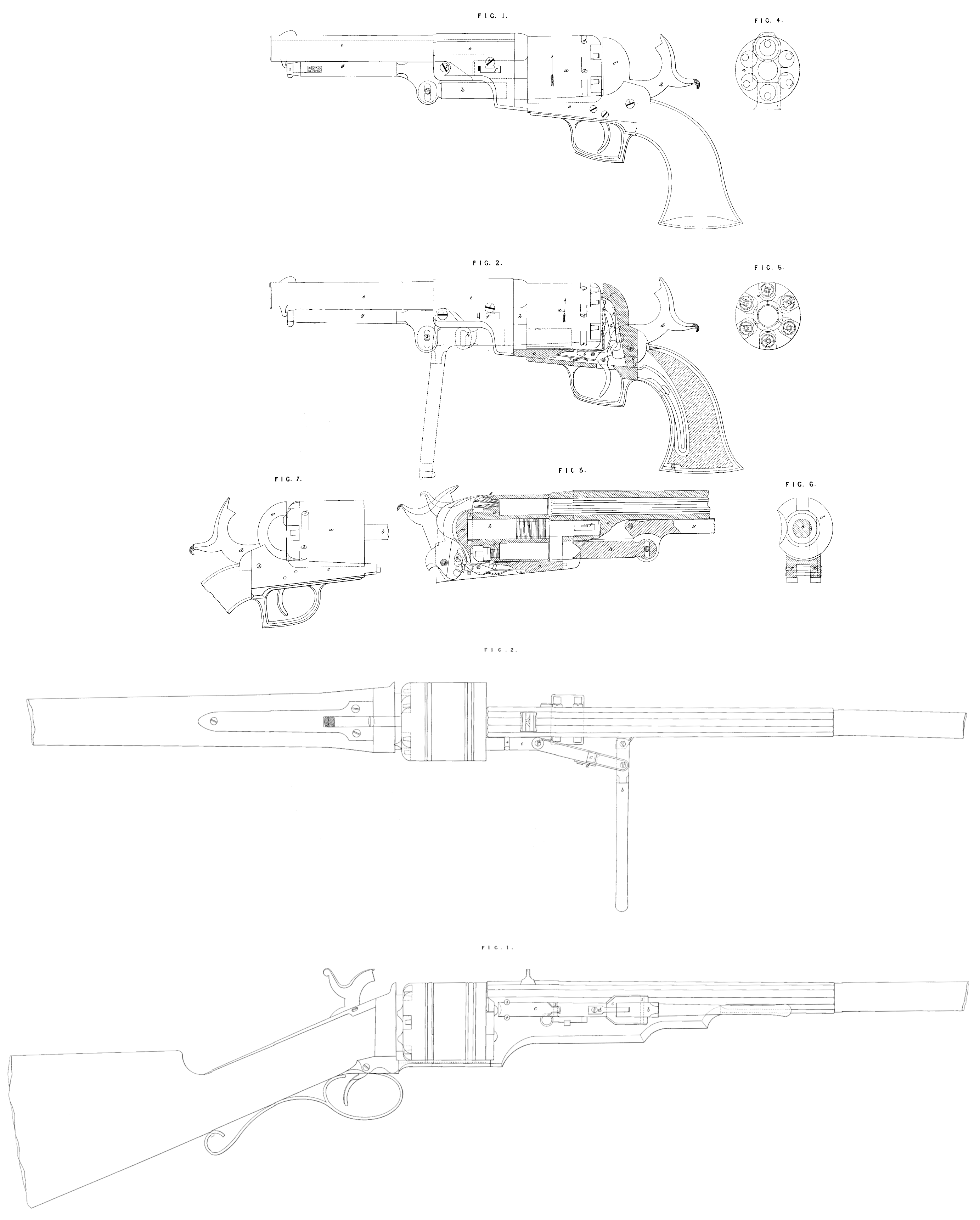
My Invention of “Improvements in fire-arms” consists in certain improvements upon that construction of guns and pistols which has a cylindrical revolving breech piece provided with a series of parallel chambers for containing a series of charges, which charges, by the revolution of the breech upon its shaft, may be successively brought into a line with the bore of the barrel and be severally discharged through the same. In the accompanying Drawing my improvements are shewn as applied to this construction of fire-arms, which formed the subject of a Patent granted to me in England on the Twenty-second day of October, One thousand eight hundred and thirty-five. Sheet I. of these Drawings represents my improvements as applied to pistols; and Sheet II. represents a rifle, carbine, musket, or shot gun with my improvements attached. Fig. 1, Sheet I., shews my improved pistol in side view; Fig. 2, is a side view, shewing the lock frame and recoil shield in section; and Fig. 3, is a longitudinal section taken through the middle of the breech and barrel. a, is the breech containing six chambers, more or less, as shewn in the end view Fig. 4; in the back of each of which a nipple is fitted (as shewn in end view at Fig. 5, and in section at Fig. 3,) to receive a percussion cap for firing the charge. This breech is supported by and is capable of turning on a spindle or arbor b, which is welded or fastened to and forms one piece with the recoil shield c*, it being in a line parallel to the axis of the barrel. The shield is itself a continuation of the lock frame c, the whole being formed out of one solid piece of metal. By referring to the longitudinal section Figures 2, and 3 and to the cross section Fig. 6, the peculiar construction of this lock frame and shield will be readily understood. The shield c*, stands up at right angles to the frame c, and forms a round head (somewhat like a bolt head) to its shaft 6. The upper part of the shield is recessed to receive the hammer d, when it is thrown forward to effect the discharge of the pistol, and a recess is also made in the piece of metal which constitutes the lock frame and shield (see Fig. 2,) to receive the parts which respectively revolve the breech to bring round the charges in a line with the barrel e, and lock the breech to the frame for the purpose of insuring that the charges shall be in a line with the barrel before the firing takes place. When the pistol is on half cock or in the position shewn at Fig. 3, the breech is free to turn round on its arbor in the direction of the arrow, Figures 1 and 2. It may then be loaded and primed with facility without being removed from its place as was formerly requisite in charging this construction of revolving breech fire-arms, a free space being left in front of the mouths of the chambers, as will be seen by referring to the end view of this breech, Fig. 4, which shews the sectional area of the barrel and its appendages in red lines. The barrel e, is supported in its place by the end of the spindle b, fitting into a socket in a bracket piece forming one with the barrel, as shewn best at Fig. 3; against the end
of this socket the spindle is made to abut, and thus to determine the exact position of the barrel with respect to the face of the revolving breech. To keep the barrel secure in its place a key f, is introduced through slots in the bracket or projecting piece of the barrel, and through the spindle b, its upper edge acting on the forward end of the slot in the spindle, and its lower edge acting upon the lower end of the slots in the bracket of the barrel ; the effect of which is to draw the barrel towards the cylinder breech and lock frame as the key is pressed in, and pins projecting from the end of the lock frame enter corresponding recesses in the bracket piece of the barrel. The key f, has a spring catch which rises when the key is forced “home,” and by its turned up end coming in contact with the edge of the slot through which it has been passed it will prevent the key from getting loose and shaking out of its place by the concussion of the firing. This object is further ensured by the insertion in the barrel piece of the screw 1, the head of which would come in contact with the turned up end of the catch if it had escaped pass the edge of the slot, and prevent it from dropping or even being drawn out; this screw must therefore be removed before the key can be displaced. Jointed to the bracket part of the barrel by a pin 2, is a lever g, which is kept up in a position parallel to the barrel by a spring catch at its other end, taking into a catch on the lower side of the barrel. To this lever a plunger h, is connected by a pin 3, taking into a slot on the outer end of the plunger. The inner end of the plunger slides in a guide made for it in the bracket piece of the barrel. This plunger is intended to act as a ramrod, and to drive the bullets or cartridges into the several chambers of the breech consecutively as they are brought in aline with the plunger. To effect this the catch or the lever g, is disengaged, and the lever is brought into the position shewn by dots in Fig. 2; the plunger is thereby driven forwards and made to ram the bullet (which has been previously inserted in the end of the chamber now brought in a line with the plunger) down into its proper place in the chamber. The plunger is then drawn back, and the next succeeding chamber brought in a line therewith, when the lever g, is again brought into the dotted position to thrust the plunger forward and ram down another charge and thus successively all the charges are acted upon. By referring to the Drawing Fig. 3, it will be seen that the mouths of the chambers and the inner end of the barrel are chamfered at their edges. This bevelling of the edges of the chambers is to prevent the lateral discharge between the breech and the barrel (which discharge is consequent upon the construction of fire-arms to which my improvements refer) from igniting the powder in the other loaded chambers; for the ignited matter, by coming into contact with the bevelled edge as it crosses the mouths of the chambers, will be deflected outward and effectually thrown off, and be prevented from reaching the powder in the chambers. The bevelling of the end of the barrel is intended to prevent its cutting the ball in its passage from the chamber. At Figures 6, and 7, it will be seen that a hollow is made in one side of the shield c*; the object of this is to expose the ends of the nipples as the breech is revolved, and thus to allow of the percussion caps being readily placed thereon.
I will now describe the arrangements of the various parts for rotating and locking the breech, and for discharging the pistol, in order that the construction of the pistol may be the better understood. The hammer d, turns on a pin 4, in the lock frame c, and it is provided with stops or catches for the end of the trigger to abut against, as usual, and hold it at whole or half cock, as required. To the hammer is jointed a hand catch i, with the spring k, attached, (see Fig. 2,) which is pressed forward into contact with ratchet teeth formed on the end of the breech, and allows the hand to recede for passing below a second tooth of the ratchet. l, is a rocking lever, supported by a pin in the lock frame c, and carrying at one end a bolt which is intended to enter at certain times into the recesses 5, 5, in the periphery of the breech, a bearing spring m, (see Fig. 3,) giving it always a tendency to rise for that purpose. The other end of this lever is made thin so as to be capable of yielding laterally and recovering its position, thus allowing a stud 6. which projects from the hammer and has a chamfered or bevelled face, to pass the lever without disturbing the position of the bolt end when the hammer moves forward to fire the charge; and yet, when the hammer is drawn back, to present an obstruction to the stud 6, and be thereby tipped into the position shewn at Fig. 3, which movement will unlock the breech. As long as the hammer remains at half cock, the breech will be free to turn upon its spindle for the purpose of being loaded; but when the stud has passed the end of the lever, the spring m will again force the bolt of the lever into its original or locking position. The action of drawing back the hammer to its farthest extent (the bolt being first relieved) will raise the hand catch i, which being brought in contact with a ratchet tooth on the breech will turn the breech round in the direction of the arrow Fig. 2, to the extent of one tooth, and thus bring up a loaded chamber in a line with the barrel; and in succession the act of cocking will bring all the loaded chambers in like manner round in a line with the barrel and hammer to be discharged. In order to insure the insertion of the bolt of the lever l, into the recesses 5, 5, as they severally come round, and thereby to hold the breech firmly while the discharge takes place, I form a shallow channel or guide up to the edge of each, as shewn in the Drawings, which will make the bolt feel its way to the recess and enter it more certainly than if it were required to fall into the recess suddenly. To prevent the fouling of the spindle and breech, I form upon the spindle a helical groove (as shewn at Fig. 3), the edges of which will more effectually prevent the smoke from passing between the breech and spindle than if the whole periphery of the spindle were in contact with the breech; and at the same time these edges will, as the breech is rotated, scrape off any matters that may have become deposited in the central bore of the breech, and deposit it in the grooves. By this means the contact surfaces will be kept clean, and the breech, which would otherwise foul after a few discharges and become fixed, will be free to turn on its spindle for a long period without requiring any cleaning.
In Sheet II., Fig. 1, is a side view; and Fig. 2, a plan view of a rifle, carbine, musket, or shot gun, with revolving breech. As the several improvements before described with reference to the pistol are equally applicable to guns for military and sporting purposes, I shall confine my further description to the modified arrangement of apparatus for ramming down the charges. In this instance, instead of the plunger being applied below the barrel it is attached to the side thereof. a, is a bracket projecting from the side of the barrel, and to it the lever b, is jointed by a pin 1; c, is the plunger, having at about the middle of its length a joint 2; it is forked at one end, and embraces the lever b, to which it is jointed by a pin 3: the cylindrical end of the plunger works between guide pins 4, 4, on the barrel; d, is a spring catch rivetted to the plunger c, and capable, when the lever b is laid parallel with the barrel, of taking in a notch cut in the bracket a. By means of this spring the ramming apparatus, when not required to be used, is retained in the position shewn at Fig. 1; but, by drawing the lever b, into the position shewn at Fig. 2, the catch will be immediately disengaged from the notch.
Having now described my several improvements upon fire-arms having breeches which revolve on a spindle parallel to the barrel, I wish it to be understood that I claim,—
First, making the lock frame and recoil shield in one and the same piece, whereby all possibility of the parts getting loose after repeated discharges is prevented.
Secondly, the general arrangement of the lock and apparatus for turning and locking the rotating cylinder breech.
Thirdly, the general arrangement of the parts whereby the operations of loading and priming may be effected without disconnecting the breech, as was heretofore requisite.
Fourthly, the application to guns and pistols of the lever apparatus for ramming down the charges into the several chambers with great expedition and effect, the same being a substitute for the loose ramrod.
Fifthly, the chamfering the mouths of the chambers and the inner end of the barrel; also the grooving of the periphery of the breech spindle; likewise the making sunk guides to the locking recesses on the periphery of the breech; and, further, the means of insuring the proper position of the barrel with respect to the face of the breech; all for the purposes herein-before described.
In witness whereof, I, the said Samuel Colt, have hereunto set my hand and seal, this Twenty-seventh day of October, in the year of our Lord One thousand eight hundred and forty-nine
SAMUEL (L.S.) COLT.
Taken and acknowledged by Samuel Colt (party hereto), at Paris, in the Republic of France, the Twenty-seventh day of October, One thousand eight hundred and forty-nine, before me.
(L.S.) THOMAS PICKFORD,
Her Britannic Majesty’s Consul at Paris.
Enrolled the Twentieth day of December, in the year of our Lord
One thousand eight hundred and forty-nine.