
Britain 538
A.D. 1853 – N° 538.
Rotating Breech Fire-arms.
LETTERS PATENT to Samuel Colt, of Spring Gardens, in the County of Middlesex, Gentleman, for the Invention of “Improvements In Rotating Breech Fire-Arms.” — Partly a communication. Sealed the 23d April 1853, and dated the 3d March 1859.
PROVISIONAL SPECIFICATION left by the said Samuel Colt at the Office of the Commissioners of Patents, with his Petition, on the 3d March 1853.
I, SAMUEL COLT, do hereby declare the nature of the said Invention or “IMPROVEMENTS IN ROTATING BREECH FIRE-ARMS” to be as follows:—
This Invention relates, firstly, to a mode of preventing the arbor or pin on which the breech cylinder rotates from fouling by the entrance of smoke between it and the cylinder. To prevent this, the forward end of the central bore of the cylinder is closed, and the pin or arbor is inserted at the rear end, it being passed through the recoil shield or other equivalent part of the lock frame for that purpose. This pin is retained in its place by a spring catch, which may be attached to or form part with the pin.
A second feature of this Invention is, that the rear end of the breech cylinder bears against a hollow screw, through which the breech cylinder pin passes. By turning this screw the position of the cylinder, as respects its proximity to the barrel, may be nicely adjusted.
In some cases, I propose to connect the barrel to the lock frame by a hinge joint, so that by throwing up the barrel the breech cylinder may be removed when its charges are expended, and quickly replaced by a loaded cylinder.
The barrel is held firmly in place by a button with cam grooves cut in it to receive and act upon a pin projecting from the barrel, and thereby bring the barrel up to its bearing against the lock frame. Or a simple wedge may be used for the like purpose.
The last feature of this Invention relates to a means of transmitting motion to a plunger, which is a substitute for the ordinary ramrod, the object being to give the plunger the required range of motion within a contracted space.
The lover which carries and works the plunger is provided at its inner end with a segment rack, which takes into a rack formed on the barrel, and forms a progressing fulcrum for the lever.
When the lever is depressed the segment rack will roll over the rack on the barrel, and drive the plunger into that chamber of the breech cylinder which is in a line therewith, and thereby ram down the ball that has been inserted therein.
SPECIFICATION in pursuance of the conditions of the Letters Patent, tiled by the said Samuel Colt, in the Great Seal Patent Office, on the 3d September 1853.
TO ALL TO WHOM THESE PRESENTS SHALL COME, I, Samuel Colt, of Spring Gardens in the County of Middlesex, Gentleman send greeting.
WHEREAS Her most Excellent Majesty Queen Victoria, by Her Letters Patent, baring date the Third day of March, in the year of our Lord One thousand eight hundred and fifty-three, in the sixteenth year of Her reign did for Herself. Her heirs and successors, give and grant unto me the said Samuel Colt, Her especial licence that I, the said Samuel Colt, my executors, administrators, and assigns, or such others as I, the said Samuel Colt, my executors, administrators, and assigns, should at any time agree with, and no others, from time to time and at all times thereafter during the term therein expressed, should and lawfully might make, use, exercise, and vend, within the United Kingdom of Great Britain and Ireland, the Channel Islands, and Isle of Man, an Invention for “IMPROVEMENTS IN ROTATING BREECH FIRE ARMS,” being partly a communication from abroad, upon the condition (amongst others) that I, the said Samuel Colt, by an instrument in writing under my hand and seal, should particularly describe and ascertain the nature of the said Invention, and in what manner the same was to be performed, and cause the same to be filed in the Great Seal Patent Office within six calendar months next and immediately after the date of the said Letters Patent.
NOW KNOW YE, that I, the said Samuel Colt, do hereby declare the nature of my said Invention, and in what manner the same is to be performed, to be particularly described and ascertained in and by the following statement, reference being had to the Drawing hereunto annexed, and to the letters and figures marked thereon (that is to say):
This Invention relates, firstly, to a mode of preventing the arbor or centre pin on which the breech cylinder of repeating fire arms rotates from fouling by the entrance of smoke or dirt between it and the cylinder, and also of facilitating the removal of the breech cylinder from the arm, and the insertion of a charged cylinder; secondly, to a mode of adjusting the position of the breech cylinder with respect to its proximity to the barrel; thirdly, to certain means of transmitting motion to a plunger which is permanently secured to the fire arm, and is to be used as a substitute for the ordinary ramrod; and, fourthly, to certain means, where the barrel is connected to the lock frame by a hinge joint, of bringing the barrel up to its bearing against the lock frame.
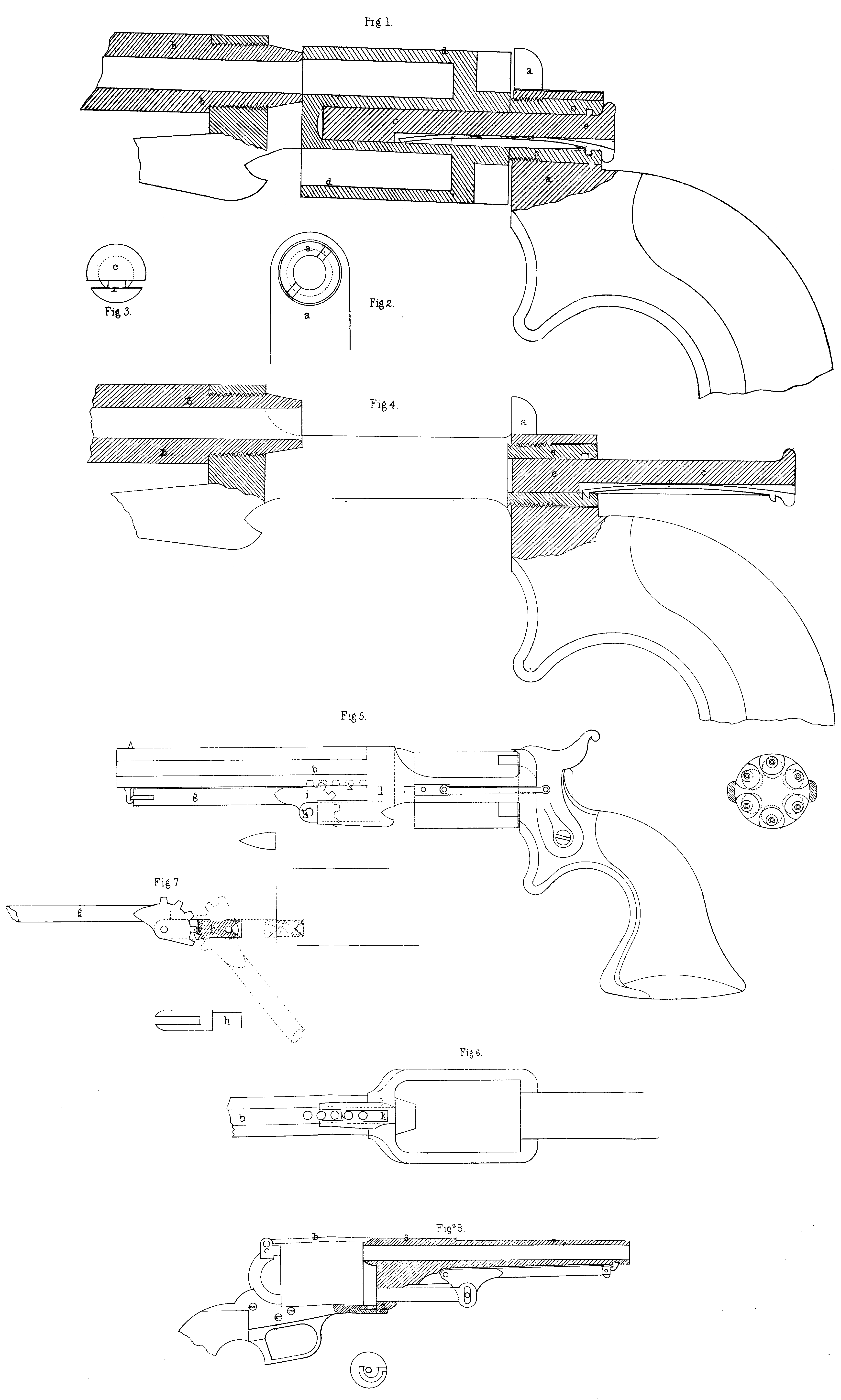
In the accompanying drawing these several improvements are distinctly set forth. Fig. 1, shews in longitudinal section so much of a repeating fire arm as will serve to explain my first and second improvements. In this Figure, a, is a portion of the recoil shield, which is formed in one piece with the frame that carries the barrel b. Through the recoil shield a hole is bored for the reception of a pin or arbor c, which projects into a central hole formed in the rotating breech cylinder d, and thereby supports that cylinder. Instead of boring the central hole quite through the cylinder, I leave the forward end solid at that part ; or I may insert a plug, if thought more convenient, and 5 thereby close the end of the central hole . By this means I prevent the possibility of the arbor c, fouling from the smoke and powder which escape from the fore end of the cylinder. In order to adjust the position of the cylinder with respect to its proximity to the barrel, so as to prevent close contact, and yet at the same time reduce, as much 10 as may be, the amount of lateral fire escaping from between the approximating parts, I enlarge the bore made in the recoil shield for the reception of the arbor c, and fit a threaded collar or hollow nut e, therein, making the inner end of the collar project through the recoil shield, and bear against the rear end of the cylinder d. When, there- 15 fore, I find it necessary to bring up the cylinder closer to the barrel, I can effect this simply by turning the collar by means of a screw -driver, it being provided with nicks for the purpose of being turned as shewn in the detached view, Fig. 2. An annular recess is cut in this collar, as shewn in the drawing, for the purpose to be presently explained. The arbor c, which passes through this collar and carries the cylinder, as above stated, is recessed to receive a spring f, which is riveted to the arbor, and is provided with catches at its opposite ends, and with a thumb piece at its outer extremity (see the end view of the arbor, Fig. 3). When the arbor is thrust home the catch at the hinder end of the spring takes into the annular recess cut in the collar e, and thereby the arbor is prevented from getting loose or out of its place ; but when the arbor is drawn back, as shewn at Fig . 4, for the purpose of removing the cylinder from the arm, the catch at: the inner end of the spring will take into the annular recess, and thereby prevent the arbor from dropping out of its bearing. To allow of the arbor being drawn back, the hinder catch must be first lifted out of the recess in the collar e ; and for this purpose the thumb piece is provided, which, by being pressed up, will raise the catch free of the recess.
The third feature of this Invention is shewn, as applied to a pistol, at Fig. 5. Instead of jointing the lever g, (which works the plunger h,) to the underside of the barrel, as described in the Specification of my Patent, dated the Twentieth day of June, One eight hundred and forty -nine, I provide the lever with a segment rack i, the teeth of which take into a rack or line of holes k, formed in the underside of the barrel b, as shewn in the plan view, Fig . 6, and thereby I obtain a creeping or progressing instead of a stationary fulcrum, the advantage of which is that the required range of motion for the plunger may be imparted thereto within a contracted space (see the diagram, Fig. 7) as compared with the stationary fulcrum. The plunger h, is made to embrace the segment termination of the lever, and it is jointed thereto by a pin. A guide is provided in the frame l, for directing the course of the plunger.
The fourth feature of the Invention is shewn at Figs. 8. Affixed to the barrel a, is a strap b, which passes over the breech cylinder, and is jointed to the recoil shield c, of the lock frame. Projecting from the underside of the barrel is an abutting piece d, which rests against the forward extremity of the lock frame. This abutting piece is furnished with a pin that takes into a groove formed in a button é, carried by a pin on the lock frame. This groove is shewn in the detached view of the button e, as of a volute form, receding gradually from the edge of the button, and approaching the centre pin. By turning this button the pin on the abutting piece of the barrel will be drawn inwards, and thus the barrel will be held firmly to and in close contact with the lock frame. Instead of this rotating button I propose to effect the same object by means of a wedge having taper edges, which, by being driven through corresponding slots cut in the abutting piece of the barrel and the forward extremity of the lock frame, will draw the parts closely together. The object of connecting the barrel to the lock frame by a hinge joint is to allow of the ready release of the breech cylinder when all its charges are expended, and the insertion of a loaded cylinder in its place ; but as this construction of arm presents insuperable inconveniences when not provided with a means of drawing the barrel up to the frame, I have designed the above contrivances for the purpose of removing one great and hitherto fatal
objection to the use of the jointed barrel.
Having now described the nature of this Invention, and the manner of carrying the same into effect, I wish it to be understood that under the above in part recited Letters Patent, I claim,—
First, constructing the breech cylinder with a stopped or closed central hole, for the purpose above set forth.
Secondly, supporting the breech cylinder by means of a centre pin or arbor projecting from the recoil shield, and capable of being drawn back to allow of the removal of the cylinder.
Thirdly, I claim the adjustment of the position of the breech cylinder with respect to its proximity to the barrel by means of a screw nut or threaded collar, which is made to bear against the rear end of that cylinder.
Fourthly, I claim the use of a creeping fulcrum for transmitting motion to the plunger employed in loading rotating breech fire arms.
And lastly, I claim the means above set forth for bringing the barrel up to its bearing against the lock frame.
In witness whereof, I, the said Samuel Colt, have hereunto set my hand and seal, the Thirteenth day of June, in the year of our Lord One thousand eight hundred and fifty-three.
SAM. COLT. (L.S)