
Britain 1552
A.D. 1855 — N° 1552.
Revolving Fire-arms and Cannon.
LETTERS PATENT to Thomas Wright Gardener Treeby, of 1, Westbourno Terrace Villa, Westbourne Terrace North, Paddington, for the Invention of “Improvements In Revolving Fire-Arms And Cannon.”
Sealed the 10th January 1856, and dated the 11th July 1855.
PROVISIONAL SPECIFICATION left by the said Thomas Wright Gardener Treeby at the Office of the Commissioners of Patents, with his Petition, on the 11th July 1855.
I, THOMAS WRIGHT GARDENER TREEBY, of 1, Westbourne Terrace Villa, Westbourne Terrace North, Paddington, do hereby declare the nature of the Invention for “Improvements In Revolving Fire-Arms And Cannon” to be as follows:—
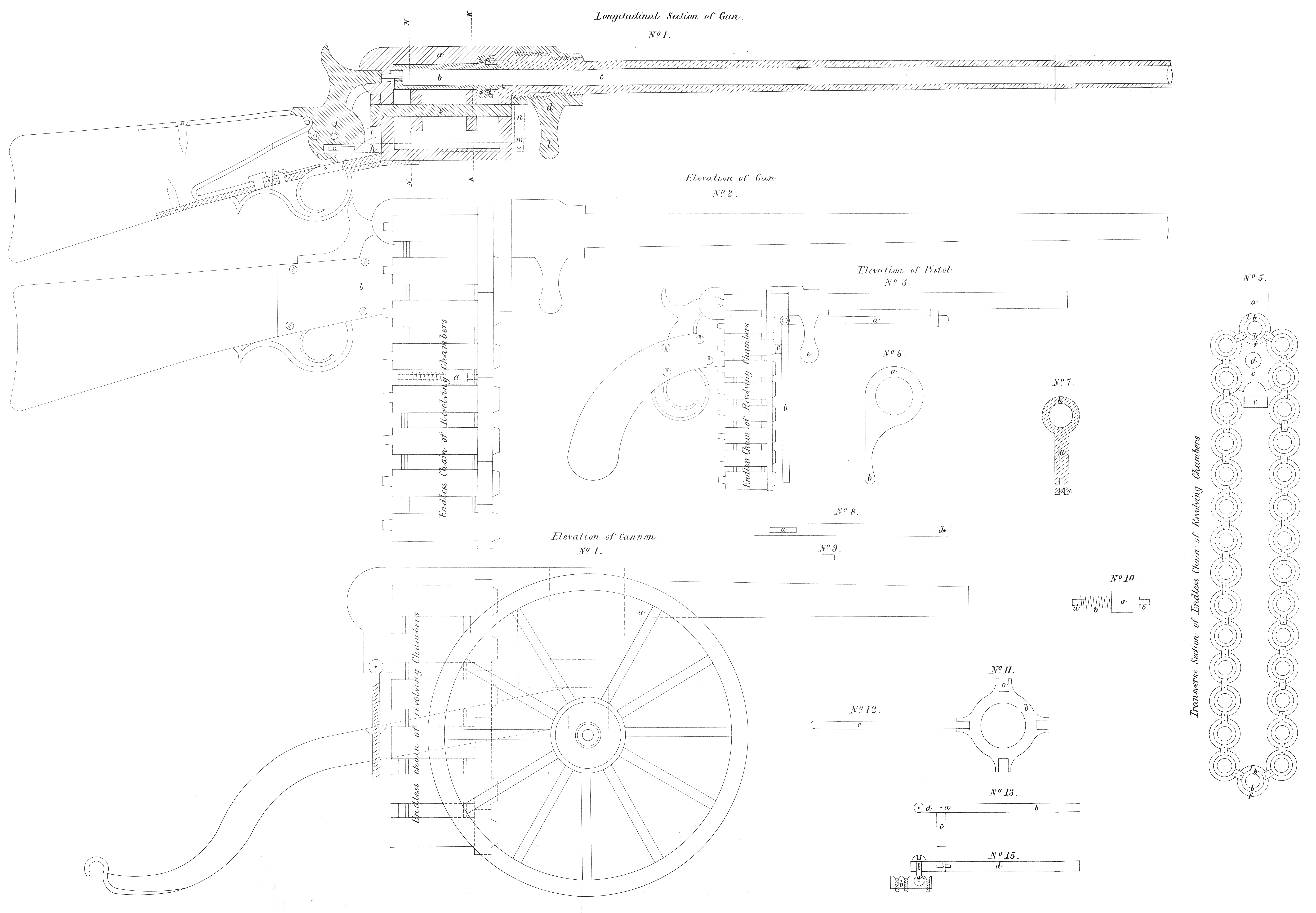
This Invention consists in substituting an endless chain of chambers for the revolving cylinder of chambers used ordinarily in revolving fire-arms. The endless chain of chambers is formed by hinging the single chambers to each other, side by side, and when in use the chambers are brought up in succession to be fired in the same manner as the chambers of ordinary revolving fire -arms are in succession brought up.
SPECIFICATION in pursuance of the conditions of the Letters Patent, filed by the said Thomas Wright Gardener Treeby in the Great Seal Patent Office on the 11th January 1856.
TO ALL TO WHOM THESE PRESENTS SHALL COME, I, THOMAS WRIGHT GARDENER TREEBY, of 1, Westbourne Terrace Villa, Westbourne Terrace North, Paddington, send greeting.
HEREAS Her most Excellent Majesty Queen Victoria, by Her Letters Patent, bearing date the Eleventh day of July, in the year of our Lord One thousand eight hundred and fifty-five, in the nineteenth year of Her reign, did, for Herself, Her heirs and successors, give and grant unto me, the said Thomas Wright Gardener Treeby, Her special licence that I, the said Thomas Wright Gardener Treeby, my executors, administrators, and assigns, or such others as I, the said Thomas Wright Gardener Treeby, my executors, administrators, and assigns, should at any time agree with, and no others, from time to time and at all times thereafter during the term therein expressed, should and lawfully might make, use, exercise, and vend, within the United Kingdom of Great Britain and Ireland, the Channel Islands, and Isle of Man, an Invention for “Improvements In Revolving Fire-Arms And Cannon,” upon the condition (amongst others) that I, the said Thomas Wright Gardener Treeby, my executors or administrators, by an instrument in writing under my, or their, or one of their hands and seals, should particularly describe and ascertain the nature of the said Invention, and in what manner the same was to be performed, and cause the same to be filed in the Great Seal Patent Office within six calendar months next and immediately after the date of the said Letters Patent.
NOW KNOW YE, that I, the said Thomas Wright Gardener Treeby, do hereby declare the nature of the said Invention, and in what manner the same is to be performed, to be particularly described and ascertained in and by the following statement thereof, that is to say:—
This Invention consists in substituting an endless chain of chambers for the 30 revolving cylinder of chambers used ordinarily in revolving fire-arms. The endless chain of chambers is formed by hinging the single chambers to each other side by side, and when in use the chambers are brought up in succession to be fired in the same manner as the chambers of ordinary revolving fire-arms are in succession brought up.
Having thus stated the nature of my said Invention, I will proceed to describe the Drawings hereunto annexed.
No. 1, longitudinal section of gun cut through the centre. A is an iron frame, with a screw cut on the end, with hole to allow the gun barrel to pass through to chamber B, which is to contain the charge; C is the gun barrel, showing the end locked back to chamber B, with a screw a little way from the end on the outside of barrel; D is a nut with lever or arm that works over the nose of iron frame and gun barrel, which forms a nut to lock the chamber and barrel together, the screw being cut right and left handed, so when the handle L is moved it will throw the gun barrel forward and the iron frame backward, thus relieving the chamber B; H is a link or strap attached to the end of the hammer below the centre on which the hammer works. This link is shown, by dotted lines leading to M, screwed to the key N of gun barrel, which works in a slot in D, No. 7 section ; the key N, being a fixture to the gun barrel, prevents the barrel from turning with the nut. When the handle L is lifted, the barrel moves forward M, N, and H, strap 15 or link, moves with it and cocks the hammer; the strap H will prevent the hammer moving towards the cap until the barrel is locked back to chamber B. At the end of the strap H is a slot S, which works through another slot in the hammer a little below the centre or pin on which the hammer moves. This slot may be cut out of the hammer, or cut out of a plate screwed on to the hammer. On the hammer there is a screw or pin, which passes through the slot S, so when the strap or link is moved forward, it moves and cocks the hammer. At the end of the chamber A, there is, a ring cupped out to receive the end of the barrel C. P is vulcanized india-rubber. The end of the chamber is coned, and the end of the barrel made to fit it, as at R; so when the barrel is pressed home by means of the put D, the chamber and barrel being a tight iron joint, and the external edge of the barrel fitting into the cup pressing on the vulcanized india-rubber, prevents all escape of gas. E is an axletree; F, F, are two wheels, as is shewn in C, of No. 5 section; G is a ratchet; I, shewn in dotted lines, is a lifter, attached to the hammer, which lifts the ratchet and brings each chamber in a direct line with the barrel.
No. 5 is a transverse section, cut through No. 1 at K, K; I, I, showing the whole of chambers and chain as they hang on the wheel C; any number may be put on, as any number will hang the same, as shewn in this section in B, B, B, B. The chain may be put together by screws or rivets, and by means of pin No. 10 the discharged chain of chambers may be unlinked, taken out of the iron frame in plate 1, and a loaded chain replaced in its stead alternately, or any number may be put together and fired off in succession one after another; they are loaded, and the charge pressed home by a ramrod.
No. 10 is a turned pin, with a shoulder at C and A, D; to the shoulder A the pin is parallel. D is first put into the chain or hole of chain, and pressed up sufficiently to allow C to enter, as shewn by a dotted line A, No. 2. B is a spring to keep the pin from dropping out.
No. 2 shows the way the endless chain of chambers hangs. B is a plate to secure and f is works of lock; the right-hand one has a shoulder for the chamber to butt against when the charge is pressed home. These plates are screwed to the iron frame that the chamber passes through; they are also screwed to a top and bottom iron strap. These straps are for fixing the stock of gun.
No. 3 shows the way the endless chain of chambers hangs in pistol, with side plates, top and bottom straps, same as No. 2
No. 4 shows the way the endless chain of chambers hang in cannon. longitudinal section, No. 1, and transverse section, No. 5, explain No. 2, No. 3, and No. 4, with the exception in No. 4. A represents a strong iron guide for barrel of cannon to pass through, and No. 11 shows a stronger nut than No. 6, with a portable lever.
No. 6 shews a transverse section of nut in D, No. 1. A is the nut ; and 6, the lever.
No. 7 is the transverse section, cut through N in No. 1 section, with slot, pin, and key shewn. A is the key; B, the gun barrel; C, the pin; D, the slot.
No. 8 is the link or strap, shewn in No. 1, H, M, that lifts the hammer. A, the slot; D, the pin that connects the link to key N in No. 1.
No. 9 is the transverse section of No. 8; No. 11 being a strong nut with socket for lever.
No. 12 is the lever and nut for cannon.
No. 13 shows the ramrod and lever, as shewn in No. 3. B, D, is the lever; C is the ramrod which has sent the charge home; D, on No. 3, is a small ball joint, which allows the lever to be turned back under the barrel on a catch which is fixed to the barrel, or it may hang down when out of use, as shewn, the ramrod being twisted round out of the way. A shews the joint or screw.
No. 15 shews the lever with ball in socket, which allows the lever to move in any direction. I further explain this by calling the joints at D, shewn in No. 3, ball joints, as they are better understood by that name.
I have in the above description explained my present Invention in combination with further improvements, for which other Letters Patent have since been granted to me, in order that my Invention may be shewn in the most perfect condition; but I wish it to be understood that under the present Letters Patent, I only claim arranging the short barrels into a chain, and causing them to be in succession brought opposite the stationary barrel, as herein described.
In witness whereof, I, the said Thomas Wright Gardener Treeby, have hereunto set my hand and seal, this Tenth day of January, in the year of our Lord One thousand eight hundred and fifty-six.
T. W. G. TREEBY. ( L.S)
Witness,
S. Carpmael.