
US 42823
UNITED STATES PATENT OFFICE.
DAVID WILLIAMSON, OF BROOKLYN, NEW YORK, ASSIGNOR TO THE MOORE’S PATENT FIRE ARMS COMPANY, OF SAME PLACE.
IMPROVEMENT IN REVOLVING FIRE-ARMS.
Specification forming part of Letters Patent No. 42,823, dated May 17, 1864.
To all whom it may concern:
Be it known that I, David Williamson, of the city of Brooklyn, in the county of Kings and State of New York, have invented, made, and applied to use a certain new and useful Improvement in Revolving Fire-Arms; and I do hereby declare the following to be a full, clear, and exact description of my said invention, reference being had to the annexed drawings, making part of this specification, wherein—
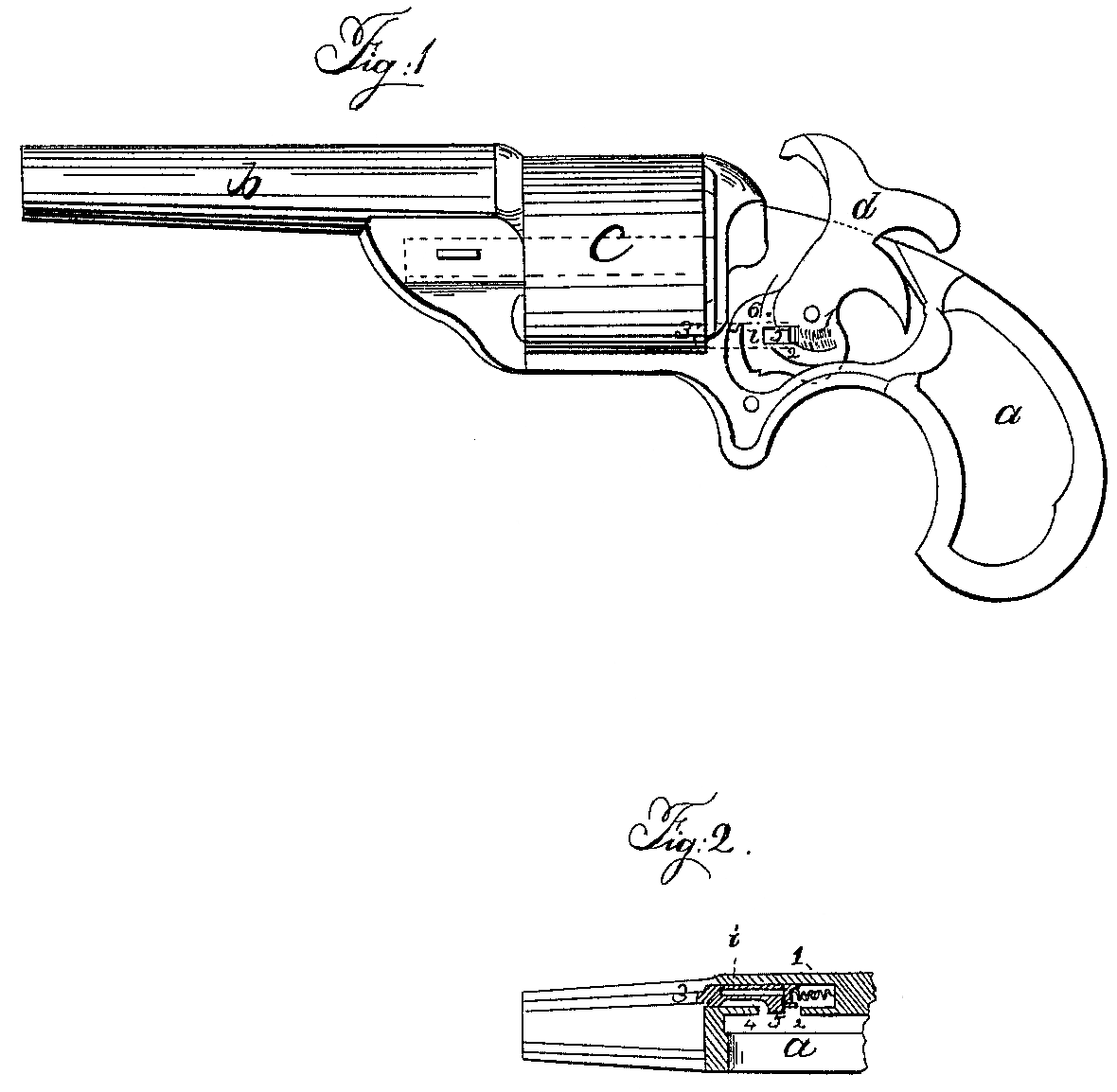
Figure 1 is an elevation of a revolving fire-arm with the lock-plate removed and the hammer in red lines, so as to represent my improvement; and Fig. 2 is a sectional plan through the stock at the locking-bolt.
Similar marks of reference denote the same parts.
Revolving fire-arms have heretofore been constructed with a bolt to take a notch in the rear end of the revolving cylinder, to hold the same while the chamber in line with the barrel is being discharged.
My invention consists in a sliding bolt formed With a spring-latch on its side adjacent to and in combination with a beveled pin on the hammer-tumbler, that crosses the bolt in the act of cocking and draws back the bolt by the latch, and in crossing the bolt in the act of firing the inclined surface of the pin presses back said latch and the spring carrying the same without moving the bolt itself.
In the drawings, a is the stock; b, the barrel; c, the cylinder containing chambers, of any desired character or number.
d is the hammer, (shown in red lines in Fig. 1) actuated by any usual mainspring, and fitted with a trigger and pawl to rotate the cylinder.
i is my improved stop-bolt, made to slide parallel, or nearly so, to the axis of the cylinder, and kept forward by a spring, 1, acting at the end of said bolt is and 2 is a cup or washer, that may be placed between the spring and bolt or attached to the end of the spring, to prevent the wire forming said spring becoming Wedged or jammed in any part of the bolt. The forward end of this bolt is made with a projection, 3, of a size and shape corresponding to a recess in the rear end of the cylinder.
The bolt i itself is slotted lengthwise to form a spring on one side, at 4, and upon which is a projection, 5, and on the hammer d is a pin, 6, the lower side of which is beveled off. (See red line, Fig. 1.) As the hammer is cocked the pin 6 moves across the path of the stop-bolt, and taking the inclined under side of the projection 5, said bolt is drawn back, and the pin 6, passing along, clears the said projection 5, and the bolt is driven forward by the spring 1 and enters the notch of the cylinder when said notch comes opposite to said bolt. As the hammer is discharged the inclined under side of the pin 6 presses back the spring side 4 of the bolt as it passes over the projection 5, and then said part 5 again springs over 6, to be acted on as before.
The bolt i may be made from a circular or flat piece of metal, and the spring 1 may be either helical, as shown, or a bent strip.
What I claim, and desire to secure by Letters Patent, is—
The combination of a sliding spring-bolt parallel, or nearly so, with the axis of the cylinder to be locked, a spring-latch on the side of said bolt adjacent to the hammer-tumbler, and a beveled pin on said hammer-tumbler, crossing said bolt in the act of cocking and firing, as and for the purposes specified.
In witness whereof I have hereunto set my signature this 13th day of January, 1864.
D. WILLIAMSON.
Witnesses:
Edwin P. Fowler,
H. N. Brush.