
US 43529
UNITED STATES PATENT OFFICE.
R. D. O. SMITH, OF WASHINGTON, DISTRICT OF COLUMBIA.
IMPROVEMENT IN CARTRIDGE-EXTRACTORS FOR REVOLVING FIRE-ARMS.
Specification forming part of Letters Patent No. 43,529, dated July 12, 1864.
To all whom it may concern:
Be it known that I, R. D. O. Smith, of Washington, in the county of Washington and District of Columbia, have invented a new and useful Improvement in Fire-Arms; and I do hereby declare the following to be a full, clear, and exact description of the same, reference being had to the accompanying drawings, in which—
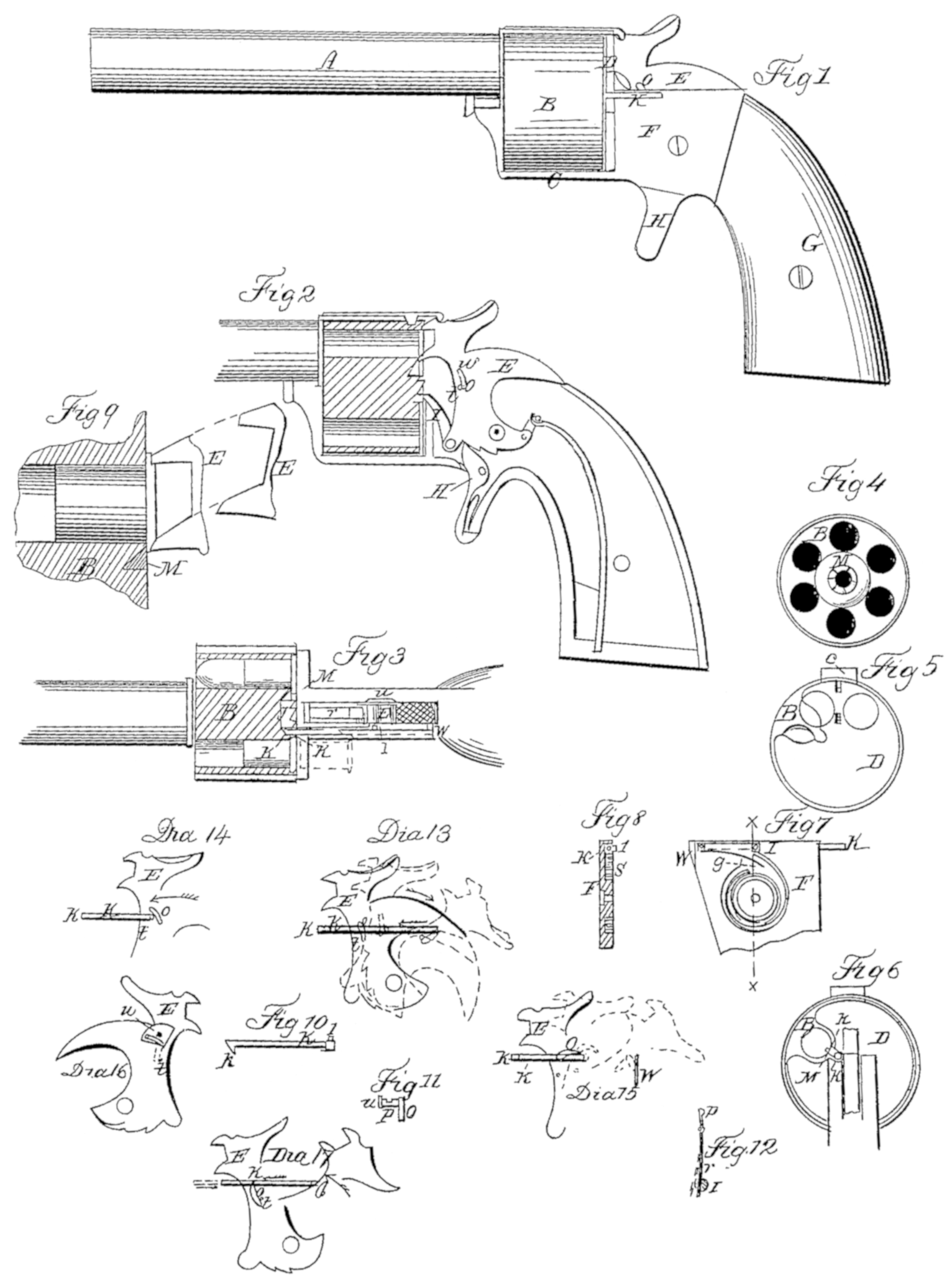
Figure 1 is a side view or elevation of a revolver having my improvement attached. Fig. 2 is a vertical longitudinal section of the same. Fig. 3 is a horizontal longitudinal section of the same. Fig. 4 exhibits the rear end of the cylinder. Fig. 5 is a rear view of the recoil plate. Fig. 6 is another rear view of the same. Fig. 7 is an inside view of the side plate. Fig. 8 is a vertical cross-section of the same through the line x x. Fig. 9 exhibits the shape and action of the noses of the hammer. Fig. 10 is a plan view of the retractor; Fig. 11, a front view of the retractor-cam. Fig. 12 exhibits the cam and dog spring. Diagram 13 exhibits the action of the cam in withdrawing the retractor and releasing it again. Diagram 14 exhibits the action of the cam when the hammer returns. Diagram 15 shows the method of setting the cam so that it will not operate the retractor when the pistol is cocked the first time. Diagram 16 is a view of the opposite side of the hammer, showing the cam-lever. Diagram 17 shows the arrangement of parts When the device is to be operated by pushing forward instead of drawing back.
The nature of my invention consists in providing a revolving fire-arm in which metallic cartridge-fixed ammunition is used with an automatic device for removing from the chamber the metallic shells after the cartridge has been exploded.
That the construction and operation of my device may be understood, I will particularly describe it.
I construct my pistol in all essential particulars similar to those now in use. The barrel, cylinder, lock, and stock are essentially the same. My improvements being entirely additional, it will only be necessary, then, to describe particularly those parts which I have added and their action.
A is the barrel; B, the cylinder; C, the frame inclosing the cylinder; D, the recoil-plate; E, the hammer; F, the removable side plate; G, the stock; H, the trigger; these parts all essentially as now made.
The first condition to be fulfilled is to cause the cylinder to revolve one stage in the shortest possible time, or with the smallest possible motion of the hammer when that is used as its motor. This I accomplish by placing the dog I as far from the pivot of the hammer as possible, in order to give it the most rapid motion. It is necessary that the cylinder should revolve one stage while the hammer is moving to the position of half-cock, and that the further motion of the hammer shall not cause or tend to cause the cylinder to move farther. This I accomplish by so arranging the position of the pivot upon which the dog I moves as to cause said center, the center of the pivot of the hammer, and the point of the dog to be in line with each other when the hammer has been moved to half-cock. The further motion of the hammer toward full-cock will then tend to draw back the point of the dog, and the cylinder will not be caused to turn any farther. With the dog so arranged it becomes necessary to construct the ratchet J on the end of the cylinder of such diameter, and with its teeth so disposed in relation to the chambers as to enable the dog to cause it to turn one stage during the prescribed motion of the hammer. The required motion of the cylinder having been secured, we may pass to the devices for removing the cartridge-shell. The first part is the retractor K, which is shown detached in Fig. 10 and in position in Figs. 1, 2, and 3 and in the diagrams.
The retractor consists of a bolt of any suitable dimension or shape, upon one end of which is the hook-head k, and upon the other end is the stud l. Surrounding the ratchet J is the triangular groove or channel M, as shown in Figs. 3, 4, and 9. The inner wall of this channel is perpendicular to the rear face of the cylinder, and its outer wall inclines from a line which just touches, but does not encroach upon the chambers, and intersects the inner wall at any suitable depth. The office of this channel is to receive the head k of the bolt K, so that when said bolt is in position the hook k will all be below the surface of the rear end of the cylinder and the point of the hook reach under the flange of any cartridge which may pass it. The bolt K is confined in a sheath, which is attached to or forms a part of the side plate, F, as shown in Figs. 1, 3, 7, and 8. It lies in a line parallel with the axis of the barrel and cylinder, and its position in regard to the axis of the cylinder is directly in a line, connecting said axis and the axis of the chamber which is next to the chamber which is in position to be fired. This is clearly shown in Fig. 6. The sheath inclosing the bolt K has a slit on its outer side running from the front end back a distance equal to the length of the retractor’s motion. Through this slit the head k projects and travels. It also has a slit on its inner side running forward from its rear end an equal distance, and through this slit the stud l projects and travels. (See Figs. 1, 3, and 7.) Attached to the under side of the rear end of the bolt K is the spring S, Figs. 7 and 8. For this purpose I prefer to use the spring known as “watch-spring,” though any other form may be made to answer. Its office is to return the retractor to its place after being drawn back, as will be hereinafter described. The manner in which I prefer to attach the spring S is clearly shown in Figs. 7 and 8.
Upon the side of the hammer E, I place the cam O. (See Figs. 1, 2, 3, 11, and diagrams.) This cam has a journal or pivot, p, in all respects, except size, like the journal or pivot of the dog I— that is, a cylindrical journal extending through the hammer, and with a portion of its surface filed down flat, as shown in Figs, 11 and 12. In this flattened notch the end of the spring r rests, and it is obvious that if the journal is then revolved in either direction the spring r must be flexed, as shown by the red lines in Fig. 12. The relative position of the dog I and cam O allows the use of a single strip of spring metal to be used for the two springs, it being confined at a central point, as shown at Fig. 12, with each end free and resting respectively upon the journal of the dog and cam. The lower end of the cam O rests upon the stop t, which in this case is placed in front, so as to prevent any motion of the lower end of the cam in that direction. Upon the opposite end of the journal p of the cam O is the lever or arm u, (see Figs. 2, 3, 11, and Diagram 16,) by means of which the cam O may be turned up into the position shown in Diagram 15, for a purpose to be hereinafter specified, in which position it will of itself remain by reason of the spring r then resting upon the cylindrical surface of the journal p, instead of the flat surface of its notch.
Metallic cartridges are frequently imperfect in the distribution of the fulminate, and it sometimes occurs that the cartridge fails to explode because there is no fulminate at the point where struck. In order to obviate this defect in some measure, as Well as to accomplish another object, which will be referred to, I propose to construct my hammer or other device with two or more noses and to strike the cartridge at as many different points, thus rendering its explosion correspondingly certain.
Practically I think two points the preferable number, because it can very seldom happen that the two opposite sides of the cartridge will be deficient in fulminate, if it is charged at all; and with two noses placed one above the other, as shown, when the pistol is not actually in use the cylinder may be so placed as to allow said noses to rest upon the rear surface of the cylinder, between the cartridges, in a common and well-known manner, thereby rendering an accidental explosion almost impossible. The point of the upper nose I make so that it will strike square upon the surface of the cartridge, as plainly shown in Fig. 9. The lower nose I construct a little beveling, the lower edge being most projected, as shown in the same figure. Now, this nose will strike the flange of the cartridge when it is only supported by the edge between the chamber and the channel M, so that to insure an explosion from this blow of the lower nose it would be necessary to bevel it in this way to cause it to conform more nearly to the surface of said channel. Another purpose is also accomplished, which will be seen further on.
Having described the construction of the various parts of my invention, I will now describe its operation.
To load the pistol the cylinder is to be revolved by the fingers and the cartridges placed in each chamber successively as it is brought to the position shown in Fig. 6, where the rear plate is cut away so as to admit the passage of the cartridge into the chamber. All the chambers having been loaded, the cylinder is brought to the position shown in Fig. 5, when the hammer, being let down, rests between the cartridges and not upon any one of them, and the recoil-plate overlaps and covers every cartridge sufficiently to prevent its removal from its chamber while the cylinder is in this position. It is obvious now that it will not be desirable to operate the retractor until one cartridge has been exploded, and to prevent said operation the lever u is turned up to the position shown by red dots in Diagram 16. This movement of u brings the calm O to the position shown in Diagram 15, in which position it will remain of itself, and while so placed it will pass entirely over the stud l without touching it; but before the hammer reaches full-cock the end of the calm O comes in contact with the plate W, which, as the hammer is still further drawn back, causes that end of the cam O to move downward until the spring r takes effect and brings it down to its normal position in contact with the stop t. Pull the trigger, the hammer descends, and the cartridge is exploded.
The effect of the blow upon the flange is shown in Fig. 9. The upper nose indents a portion in the usual way, while the lower nose not only indents, but bends it down, so that the lower surface of the flange is just at that point made slightly hooked in form, as shown in the same figure. The cam O, when the hammer descends, passes over the stud l, as shown in Diagram 14. The stud striking it on the front side, the can moves backward and slips over the stud, the spring r returning it to its position instantly upon passing clear of the stud. The pistol having been fired once, the act of recocking the piece preparatory to another discharge rotates the cylinder and removes from its chamber the shell of the cartridge which has just been exploded. This is accomplished as follows: As has been specified, the motion of the hammer from rest to half-cock causes the cylinder to revolve one stage, and this brings the cartridge which has just been fired into the position shown in Figs. 3 and 6, or so that the flange projects over the hook k, as there shown. When, now, the hammer moves from half-cock to cock the calm O comes in contact with the stud l, (see Fig. 3 and Diagram 13, in which latter the black lines indicate the position at rest, the red at half-cock, and the blue at full-cock) and presses it backward, causing the bolt K to slide in its sheath, so as to withdraw the head k from the channel M, and as the hook k extends under the flange of the cartridge, and at that particular part where the flange has been bent down a little so that the hook it cannot slip off, and the cartridge-shell is of necessity withdrawn from its chamber by said hook, and withdrawn sufficiently far to be entirely clear of the chamber, whence it will fall of its own Weight to the ground. (See Fig. 3.) The position of the parts are so arranged that the retractor will be moved far enough to withdraw the cartridge entirely from the cylinder before the hammer reaches the position of full-cock, and they are also so arranged that immediately after having withdrawn the retractor sufficiently far, as above stated, and before the position of full cock has been reached, the upper end of the cam O will have passed below the plane of motion of the stud l, and said stud will therefore be released from the can O, and the spring S will instantly return the bolt K to its normal position, with the head k resting in the channel M. If it be desired, a new cartridge may now be inserted in this vacant chamber; or, if it be not desirable or there is not time, the whole of the chambers may be fired in succession, each shell being removed by the act of recocking the piece immediately after each explosion.
The advantages of a device which will operate without consuming time and extra movements are too obvious to need comment, and I will simply point out the fact that by my plan the frame of the pistol may be made solid and, to all intents and purposes, the cylinder unremovable, thereby rendering it possible to construct the pistol with greater strength and solidity.
My invention is also applicable to those pistols in which metallic cartridges are used, and which are inserted at the front end of the cylinder. In that case the motion of the bolt K. is reversed, being pushed forward by the descent of the hammer or by any suitable device which might be operated by the motion of the hammer while the pistol is being cocked, the channel M would be dispensed with, and the cylinder might be operated without any change of parts. The stop t would then be placed behind, instead of in front of the cam O, and otherwise the arrangements would be similar. The bolt K might be caused to operate through the orifice in the rear of the chamber through which the nose of the hammer had operated in exploding the cartridge. This is sufficiently illustrated by Diagram 17.
Having described my invention, what I claim as new, and desire to Secure by Letters Patent, is—
1. In combination with an automatic device for removing the shell of an exploded metallic cartridge from its chamber in the cylinder, a device by means of which said automatic de vice may be prevented from operating when it is not desirable that it should operate.
2. In combination with the hammer of the lock of a revolving fire arm, the cam O, the bolt K, and spring S, substantially as described, and for the purpose set forth.
3. In combination with the bolt K, the channel M, substantially as described, and for the purpose set forth.
4. In combination with the cam O, the lever u, and plate W, substantially as described, and for the purpose set forth.
5. In combination with the cylinder of a revolving fire-arm, a device to cause the said cylinder to revolve one stage during the first half of the motion of the hammer from rest to full-cock.
R. D. O. SMITH.
Witnesses:
John S. Hollingshead,
John D. Bloor.