
US 160551
UNITED STATES PATENT OFFICE.
DEXTER SMITH, OF SPRINGFIELD, MASSACHUSETTS.
IMPROVEMENT IN REVOLVING FIRE-ARMS.
Specification forming part of Letters Patent No. 160,55, dated March 9, 1875; application filed January 21, 1875.
To all whom it may concern:
Be it known that I, Dexter Smith, of Springfield, in the State of Massachusetts, have invented a new and useful Improvement in Revolving Fire-Arms; and that the following is a full, clear, and exact description and specification of the same.
The object of this invention is to extract all the shells at once from the chambers of a cylinder; and, for the effectual accomplishment of this object, my invention consists of an ordinary extractor-plate, disposed upon the rear end of a hollow or tubular stem, which is arranged to slide upon the center-pin supporting the cylinder. The latter has a limited movement upon the hollow extractor-stem, and a peripheral shoulder is made upon a projection on the rear side of the extractor-plate, against which the hooked end of a catch impinges, to hold the extractor stationary when the cylinder is moved forward to extract the shells.
The hooked catches are each provided with a protuberance, which impinges against the side of the hammer, being pressed in against the hammer by a spring, and the hammer, having a recess made in the side, operates the catches to disengage them from the peripheral shoulder on the projection at the rear of the extractor-plate.
In order that the invention may be fully understood I will describe it, having reference to the figures shown in the accompanying drawing, and to the letters marked thereon.
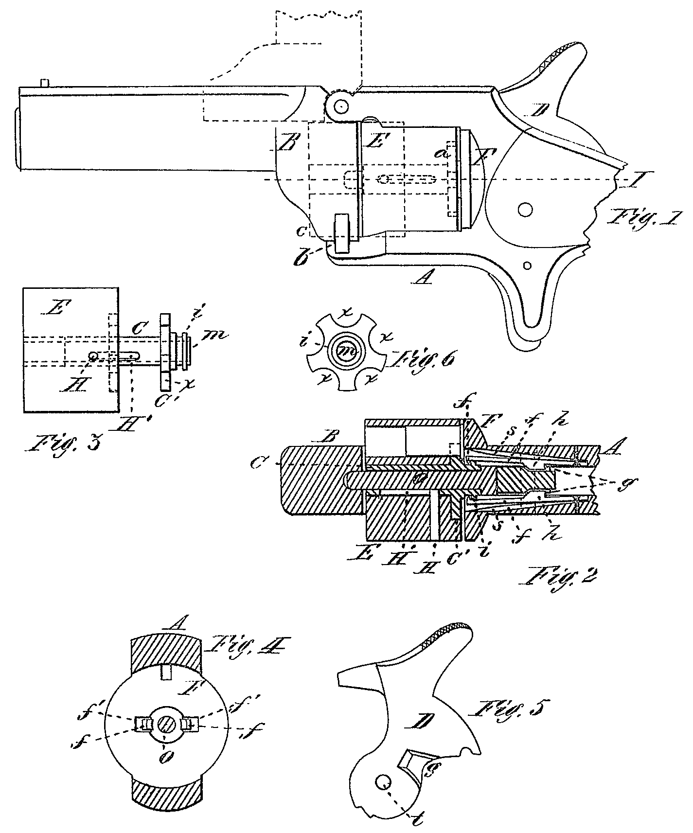
Figure 1 represents a revolving fire-arm having my invention applied thereto. Fig. 2 is a horizontal longitudinal section at line I. Fig. 3 is a side view of the cylinder with the extractor and stem drawn out of the cylinder. Fig. 4 is a transverse vertical section at line A’, showing the front of recoil-plate. Fig. 5 is a side view of the hammer, showing the recess in the side by which the catch is operated; and Fig. 6 is a rear view of the extractor-plate.
E is the chambered cylinder, having a central hole, in which is fitted to slide freely therein the stem C, which is made hollow, and arranged to slide upon the center-pin O, the latter being made upon, and extending forward from, the recoil-plate F. The extractor-stem is made to give a rotary motion to the cylinder by a slot, H’, in the stem, and pin H extending through the cylinder and into the slot, or by making the central hole in the cylinder prismatic, and the stem C of a corresponding form, or by connecting the two by any proper means. Up on the rear end of the stem C is made the extractor-plate C’, which is of the form shown in Fig. 6; and upon the rear side of this plate is a projection, n, upon the extreme end of which are made the crown ratchet-teeth, with which the dog engages to revolve it by the movement of the hammer, and around which extends the peripheral shoulder i. The recoil plate F is perforated at f’ on either side of the center-pin O, and a catch, f, is secured within the frame A on either side of the hammer D, and the catch is provided with a protuberance, h, at the side of the hammer, and also with a hook projection extending inward at the extreme end, and the catch is pressed inward by a spring, s, causing the protuberance h to impinge against the hammer, in the side of which is made a recess, g.
The operation of the invention is as follows: The barrel B being tilted upward, as shown in dotted lines in Fig, 1, the cylinder, with its extractor, is removed from the center-pin by raising the hammer slightly. The shells are then inserted into the chambers, while the extract or-plate C’ is in place, against the rear of the cylinder, and the latter is then replaced upon the Center-pin O, the hook projection upon the outer end of each catch f being forced into its position in front of the peripheral shoulder i as the cylinder is pressed back against the recoil-plate, and the hammer let down.
If the extreme end of the catch f is beveled in Ward, the catch will snap into place in front of the shoulder i without raising the hammer. The shells may then be all withdrawn at once by tilting the barrel up, as before, and drawing the cylinder forward. While this is being done the protuberance h on the catch f is pressed into the recess g in the side of the hammer, the latter being down; and the hook projection on the extreme end of the catch f being thus held in front of the peripheral shoulder i, the the extractor-plate C’ is held stationary while the cylinder is moved forward, and the shells are all withdrawn from the chambers of the cylinder at once, and drop out of the extractor-plate. After this is done the hammer is raised a little, which causes the protuberance to ride out of the recess g’ and against the thicker part of the hammer, which forces the catches outward, and releases them from contact with the front side of the peripheral shoulder i, and the extractor-plate C is then free to slide forward and be removed with the cylinder.
One or more of the catches f may be used; and if two are used, they may be arranged one on each side the hammer.
What I claim as new is—
1. The extractor-plate C’, having the hollow stem C, arranged to move upon the center-pin O, and within the cylinder E, and provided with the peripheral shoulder i, in combination with one or more catches, f, arranged within the recoil-plate and frame, and operated by the movements of the hammer, substantially as described.
2. The extractor-plate C’, having the hollow stem C, arranged to move upon the center-pin O, and within the cylinder E, and provided with the peripheral shoulder i, in combination with one or more catches, f, to hold the extractor stationary while the shells are being with drawn, substantially as before set forth.
DEXTER SMITH.
Witnesses:
T. A. Curtis,
C. E. Buckland.