
US 162208
UNITED STATES PATENT OFFICE.
ROLLIN WHITE, OF LOWELL, MASSACHUSETTS.
IMPROVEMENT IN REVOLVING FIRE-ARMS.
Specification forming part of Letters Patent No. 62,20s, dated April 20, 1875; application filed February 4, 1875.
To all whom it may concern:
Be it known that I, Rollin White, of Lowell, in the county of Middlesex and State of Massachusetts, have invented certain new and useful Improvements in Revolving Fire-Arms; and I do hereby declare that the following is a full, clear, and exact description thereof, reference being had to the accompanying drawings and letters of reference marked thereon, making a part of this specification.
The nature of my invention relates to an improvement in fire-arms; and it consists in the arrangement and combination of parts, which will be more fully described hereafter.
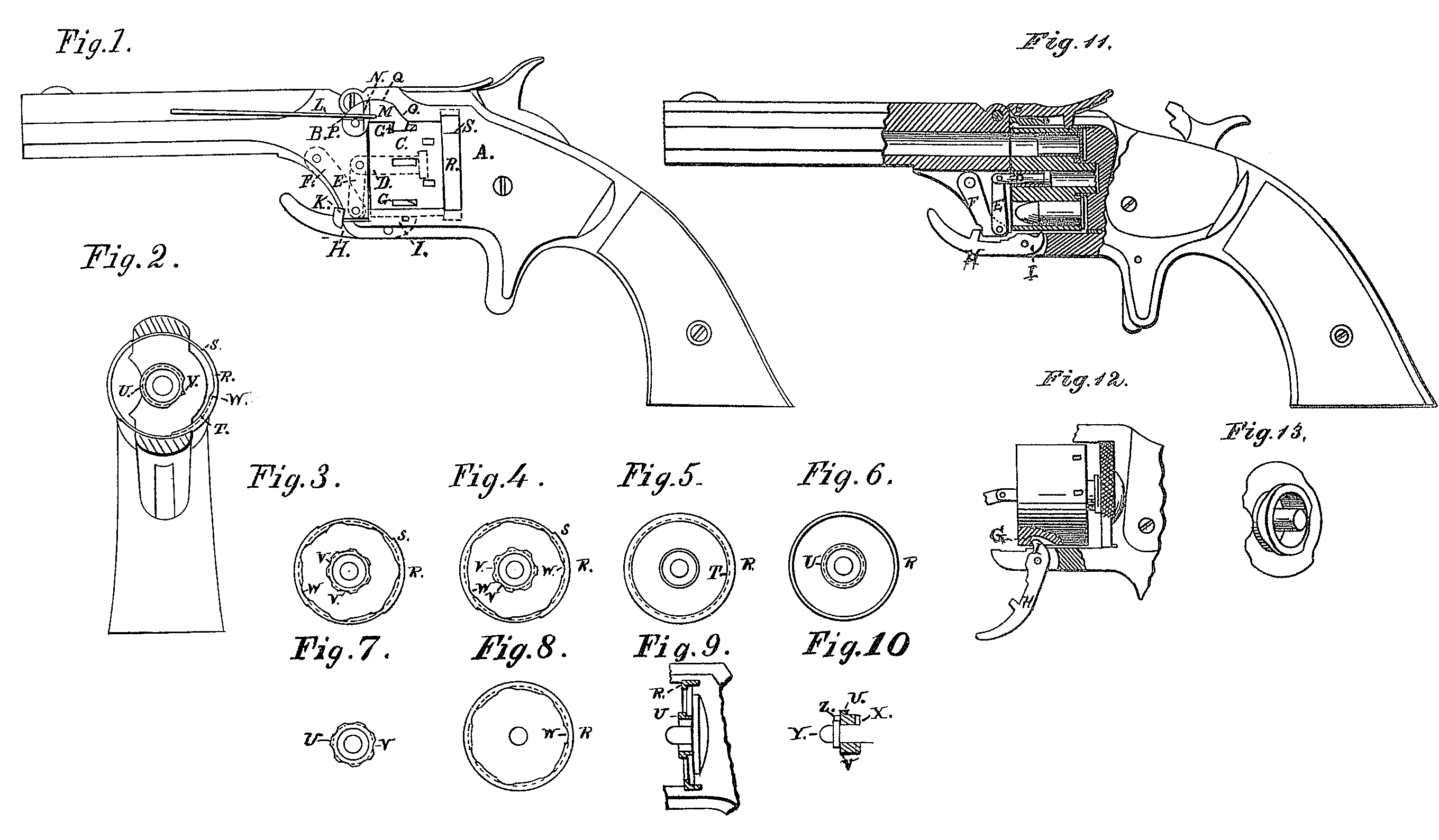
Figure 1 is a side view of my improvement, Fig. 2 is a front view of the recoil-shield, the multiple cartridge-extractor, and abutment. Figs, 3, 4, 5, and 6 are front views of the cartridge-extractor, representing the different forms and positions of the same. Fig. 7 is a view of the central cartridge-extractor. Fig 8 is a front view of the external cartridge-extractor. Fig. 9 is a longitudinal section of the cartridge-extractors, Fig. 10 is a longitudinal Section of the cartridge-extractor, ratchet, and base-pin. Fig. 11 is a longitudinal section of my improvement, showing cartridge in the upper chamber, with flange behind both central and external extractor, and cartridge in lower chamber free from both extractors. Fig. 12 is a side elevation, showing the catch adapted as a lever for starting the cylinder. Fig. 13 is an enlarged perspective view of the central cartridge extractor.
A represents the lock-frame; B, the barrel; C, the cylinder; D, the central pin on which the cylinder revolves. This pin is loosely fitted in the cylinder, so that it may turn freely thereon, and this pin is connected to the barrel by the toggle-joint E and F. The barrel B is hinged to the lock-frame, and as it swings from a line of the chambers the toggle joint will open until the bar F comes in contact with a shoulder in the barrel, and as the barrel swings farther to about right angles it operates as a lever, and forces the cylinder from the breech and from the cartridge-extractors R and U, and by this means draws the cartridge from the chambers. By means of the toggle-joint the barrel is attached to the cylinder, and by swinging up the barrel the cartridge-shells will be extracted, and the cylinder can be removed from the frame and recharged, and returned to its place for firing. As the barrel swings back to the line of the chamber the lever H locks the barrel to the frame. G represents a shoulder on, or a notch in, the cylinder, for a hook, stud, or lever to press against and force the cylinder from the breech or cartridge-extractor. M is a hook fastened to the barrel by a pivot, and as the barrel swings up this hook comes against the shoulder G, and forces the cylinder from the recoil-shield or the cartridge-extractor. As the barrel swings up, the hook turns On its pivot, the notch on the hook is brought in line with the spring L, and it enters the recess N or O in the hook, and holds it free from contact with the cylinder. This spring also acts on a cam, Q, on the back of the hook M, to hold it against the notch or shoulder on the cylinder when desired. The notch on the hook is made hooking, and the shoulder on the cylinder to correspond. By this form the hook will not slip off when force is applied to the lever or barrel. H represents the lever, pivoted to the lock-frame, with a projection, I, and forms a locking-bolt. By swinging down the lever H the locking-bolt K slides off of the shoulder on the projection of the barrel, and leaves the barrel free to swing up, and liberating the cylinder, while the projection I presses against the shoulder G, and forces the cylinder from the cartridge extractor, and by this means draws out the cartridge shells. R represents an annular abutment and partially-rotating cartridge-extractor. In Fig. 2 the line of the abutment R is opposite to the flange on the central cartridge-extractor U. This annular abutment is attached to the lock-frame, and as the cylinder is forced from it, and the flange or projection, the cartridge shells will be drawn completely out of the chambers before the front ends of the shells can tip enough to let the rim of the shells slide out of the abutment and off from the flange.
The space between the abutment and the flange is of less diameter than the rim on the cartridge. This space should be slightly larger than the diameter of the shell and one half of the rim, and then it will be impossible for the rim of the cartridge to pass out be tween the abutment and the flange until the shell is out of the chambers. On one side of this abutment, in Fig. 2, is represented a projection or flange, T, and opposite to it an abutment, for the same purpose as above described. In Fig. 2 the central and external abutments are opposite to each other at V, and a cartridge in the cylinder. When it is put into the lock-frame and taken out, the rim will slide in and out between the abutments, and Will not be withdrawn upon moving the cylinder; but by turning the abutment R it will bring the shoulder S against the lock-frame, and the flange or projection will come opposite to the abutment V, and the cartridge will be extracted by forcing the cylinder from the breech or cartridge-extractor. These changes are more clearly represented in Figs. 3 and 4. In Fig. 3 the projections or flanges and the abutments or recesses are opposite to each other, and a cylinder charged can be put into its place or taken off without extracting the shell, as the rim of the shell will be free to slide in and out between the abutments; but by turning the cartridge-extractor R’ as represented in Fig. 4, or turning the cylinder to its locking-bolt, ready to fire the pistol, and the cylinder is then forced off from the cartridge-extractor, the shells will all be thrown out of the chambers. The extractors, as represented in Figs. 7 and 8, can be used separately, or only one of them, and accomplish the Same purpose in starting the shell from the chamber; but neither of them, separately, Will be sure to draw all the cartridge shells completely out of the chambers unless the cylinder is jerked out from the frame or moved with great velocity. Fig. 5 is a view of the external cartridge-extractor with a continuous flange, and a central abutment without flange. Fig. 6 represents an external abutment and a continuous flange on the central extractor, with the cartridge-ejector and abutments, as represented in Figs. 5 and 6. The cylinder is charged while in the lock-frame, and through an opening in the recoil-shield. The central cartridge-extractor U is attached to the breech or recoil-shield, and has a projection or flange on a section of it, and on this flange is a cam. The other section W forms an abutment for the rims of the cartridges. The projection or flange and the abutment are between the chamber and the central portion of the rear end of the cylinder. The projection or flange comes close to the chamber, and in front of a section of the rim of the cartridges in the cylinder. By revolving the cylinder the cam on the flange will start each cartridge separately, or, by forcing the cylinder from the cam on the cartridge-extractor, the cartridges will be started successively from the chambers. Figs. 9 and 10 are central longitudinal sections of cartridge-extractors R and U, abutment V, loose pin Y, projection or coupling pin Z, and ratchet X. In some cases it is desirable to remove the cylinder from the pistol frame while charging it, and in other cases it is not; or it may be attached to the barrel, and therefore I have represented various forms and means of carrying out my invention.
Having thus fully described my invention, what I claim as new, and desire to secure by Letters Patent, is—
1. The combination, substantially as described, of a revolving cylinder, an extractor for withdrawing cartridges therefrom, and a lateral abutment, for the purposes set forth.
2. In a fire-arm, a revolving cylinder, a central extractor or abutment, and an annular movable abutment or extractor, when combined for operation substantially as described.
3. The combination. in a revolving fire-arm, of a frame having projecting therefrom a hollow fixed or non-rotating centrally-arranged cartridge-extractor, a revolving chambered cylinder, and a lever for drawing or starting the cylinder away from the recoil-shield and extractor, Substantially as shown and described.
4. In a revolving fire arm, having a non-rotating central cartridge-extractor, the combination there with of a cam for successively starting the cartridge as the cylinder revolves, substantially as set forth.
5. The combination, in a fire-arm, of a revolving cylinder, a toggle-joint, and a hinged barrel, adapted to withdraw the cylinder directly away from an extractor fixed to the recoil shield, substantially as set forth.
6. In combination with a revolving and sliding cylinder provided with shoulders or notches, a hook and lever or swinging barrel for starting the cylinder, substantially as specified.
7. In combination with a revolving cylinder and hinged or swinging barrel, the catch-lever H, adapted to operate as a means of starting the cylinder, the construction and operation being substantially as described.
ROLLIN WHITE.
E. L. White,
Carroll. T. Jones.