
USA 163032
UNITED STATES PATENT OFFICE.
DEXTER SMITH, OF SPRINGFIELD, MASSACHUSETTS.
IMPROVEMENT IN REVOLVING FIRE-ARMS.
Specification forming part of Letters Patent No. 63,032, dated May 11, 1875; application filed January 21, 1875.
To all whom it may concern:
Be it known that I, DEXTER SMITH, of Springfield, in the State of Massachusetts, have invented a new and useful Improvement in Revolving Fire-Arms; and that the following is a full, clear, and exact description of the same.
The object of this invention is to extract all the shells at once from the cylinder after the discharge; and to this end my invention consists of a disk or plate arranged at the rear or pins extending into the cylinder, upon which end of the cylinder, and provided with slides or pins extending into the cylinder, upon which the latter is supported and guided as it is moved toward and from the plate; and the plate or disk is of the same general diameter as the cylinder, with a shoulder around its periphery, and with recesses therein corresponding in size to the outer half of the several chambers in the cylinder.
The recoil-plate is provided with one or more grooves, extending outward from a point near the rear of the center-pin, in each of which operates a hook or catch, which is held into its position by a spring, but which is moved outward by a cam on the hammer, so that catches are each made to spring inward and grasp the disk at its peripheral shoulder; and when the barrel is unclasped from the frame, and the cylinder pulled forward, the disk is held stationary by the catches, and the shells all extracted from the chambers of the cylinder at once. The hammer being then thrown back, the cam thereon releases the catches, and both the cylinder and extractor are removed for loading.
In order that the invention may be fully understood I will proceed to describe it, having reference to the several figures shown in the accompanying drawing and the letters marked thereon.
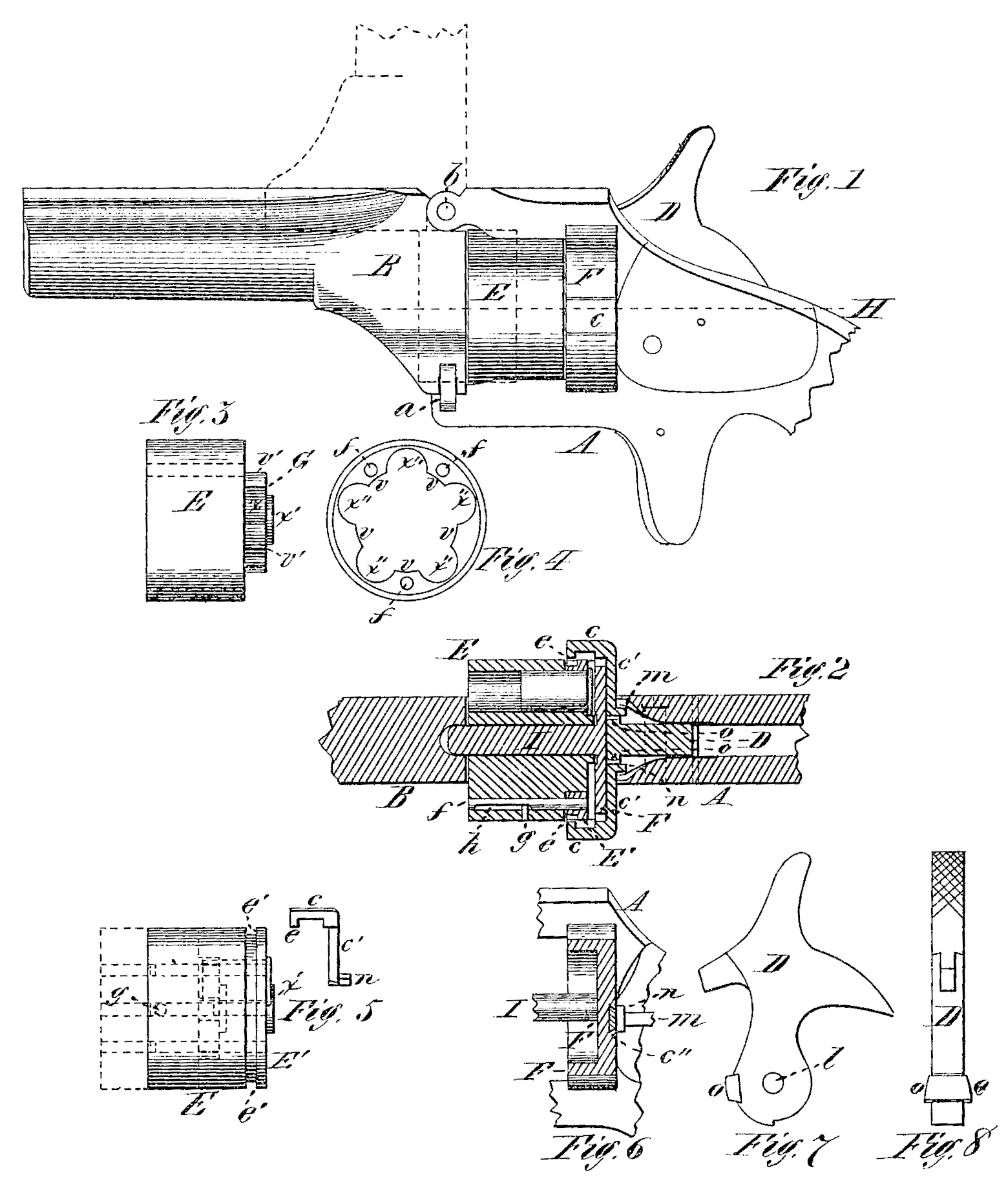
Figure 1 is a side view of a revolving pistol having my invention applied thereto. Fig. 2 is a horizontal longitudinal section at line H. Fig. 3 is a side view of the cylinder with the extractor plate or disk removed. Fig. 4 is a front view of the extractor-plate. Fig. 5 is a side view of the cylinder with the extractor-plate attached and shown in connection with the catch or hook. Fig. 6 is a vertical longitudinal section through the recoil-plate and shank of the catch. Fig. 7 is a side view of the hammer, slowing the cam there on; and Fig. S is a front view of the same.
E is the cylinder, provided with the central projection G at the rear end, which extends outward from the axis of the cylinder to a point about midway the diameter of the several chambers, and the central extended part x’ may have the usual crown-teeth provided, by which to give the rotary movement to the cylinder by the cocking of the hammer. The extractor-plate is shown in Fig. 4, in which the central part is removed and the space occupied by the projecting part G of the cylinder, the recesses x” corresponding with the outer half of the chambers x of the cylinder; and the pins fare made fast to the extractor plate, and extend through, or partially through, the cylinder, serving as a support or guide upon which the cylinder slides to and fro. A portion of one or all of-the pins may be flattened, as shown at h in Fig. 2, and a small pin, g, inserted in the cylinder, to limit the movement of the cylinder.
The recoil-plate F (shown in Fig. 6) is recessed at F in front, to receive the rear end of the cylinder, or so much thereof as is occupied by the extractor-plate E’ and a groove, c”, is made in the recoil-plate F at the rear side, which preferably is made dovetailed in its cross-section, into which is fitted, to slide freely, the shank c’ of the catch c, and the latter extends forward, being of the same general form as the section of the recessed recoil-plate F, and its front end is provided with the hook projection e, which engages with the peripheral shoulder e’ of the extractor-plate.
The inner end of the shank c’ of the catch engages with a spring, m, secured inside the frame in any proper manner, by means of which the catches c are held against the peripheral shoulder e? of the extractor-plate. A cam, o, is made upon the lower front side of the hammer— one on each side, if two catches are used— which operates to force each catch outward, to disengage it from the shoulder e’, whenever the hammer D is locked or drawn back.
It may be found in practice that one catch, c, may be quite sufficient to hold the extractor-plate while the shells are being drawn out; but whether one catch or more is used, the operation is quite the same, and should more than two catches be used the same number of cams, o may be arranged upon the hammer concentric with the pivot-hole l to operate the catches.
The operation of my invention is as follows: The chambers of the cylinder may be loaded with cartridges on removing the cylinder in the usual way by unclasping the clasp a, and turning the barrel upward, as shown in dotted lines in Fig. 1, the shells being inserted into the extractor-plate F’ and cylinder, with the flange of the shells against the extractor-plate, as shown in Fig. 5. The cylinder is then placed upon the center-pin I, and pressed back against the recoil-plate, in which operation the ends e of the catches c move in forward of the peripheral shoulder e’. This part of the operation is somewhat facilitated by making the front part of said ends e beveled. The barrel B is then secured to the frame A by the clasp a, and the arm may then be discharged. After the discharge the barrel is turned upward again, as shown in dotted lines in Fig. 1, and the cylinder being then pulled forward, the extractor is held stationary by the catches c, and the shells are extracted from the chambers, and are free to drop out. The hammer being then drawn back, the cams othereon force the catches c outward, and being thus disengaged from the peripheral shoulder, the extractor and cylinder may be drawn forward and of the center-pin I, and the chambers again loaded with cartridges, and the cylinder is then replaced as before. The catches e, in stead of being arranged on the outside of the recoil-plate, as shown in Figs. 1 and 2, may be arranged inside, so that they may not be seen, in which case dirt will be less liable to get into the working parts. Instead of the spring on, to cause the catch c to move inward, the projection in on the inner end of the shank c’ may move in an inclined or oblique groove made in the front edge of the hammer, in which-case the catch c will be moved both in – and out by the movement of the hammer alone, in drawing it back and letting it down again.
Having thus described my invention, what I claim as new is—
1. An extractor-plate, E’, provided with a peripheral shoulder, e’, combined with a chambered cylinder, and arranged to be held stationary by one or more catches, c, operated in the rear of the extractor, substantially as described.
2. An extractor-plate, E’, provided with a peripheral shoulder, e’, combined with a chambered cylinder, and arranged to be held stationary by one or more catches, c, while the cylinder is moved forward longitudinally to extract the shells, and operated by the movements of the hammer, substantially as described.
3. The combination of the extractor-plate E’, provided with a peripheral shoulder, e’, the cylinder E, and the recessed recoil-plate F, to receive said extractor-plate, substantially as described.
DEXTER SMITH.
Witnesses:
T. A. Curtis,
C. E. Buckland.