
US 196491
UNITED STATES PATENT OFFICE.
DEXTER SMITH, OF SPRINGFIELD, MASS, ASSIGNOR TO DANIEL B. WESSON.
IMPROVEMENT IN REVOLVING FIRE-ARMS.
Specification forming part of Letters Patent No. 196,491, dated October 23, 1877; application filed September 27, 1877.
To all whom it may concern:
Be it known that I, Dexter Smith, of Springfield, in the State of Massachusetts, have invented a new and useful Improvement in Revolving Fire-Arms; and that the following is a full, clear, and exact description there of, reference being had to the accompanying drawings, making a part of this specification, and to the letters of reference marked thereon.
My invention relates to an ejector for revolving fire-arms; its object being to first start the shells from the chambers of the cylinder by a slow or positive movement, and, after they are so started, to eject them entirely from the chambers by a quick movement.
To this end my invention consists of an ejector-stem extending through, or nearly through, the cylinder at its forward end, in connection with a bolt, spring, and latch, arranged to be operated by projections in the joint where the barrel is hinged to the frame, all of which will be more fully hereinafter described.
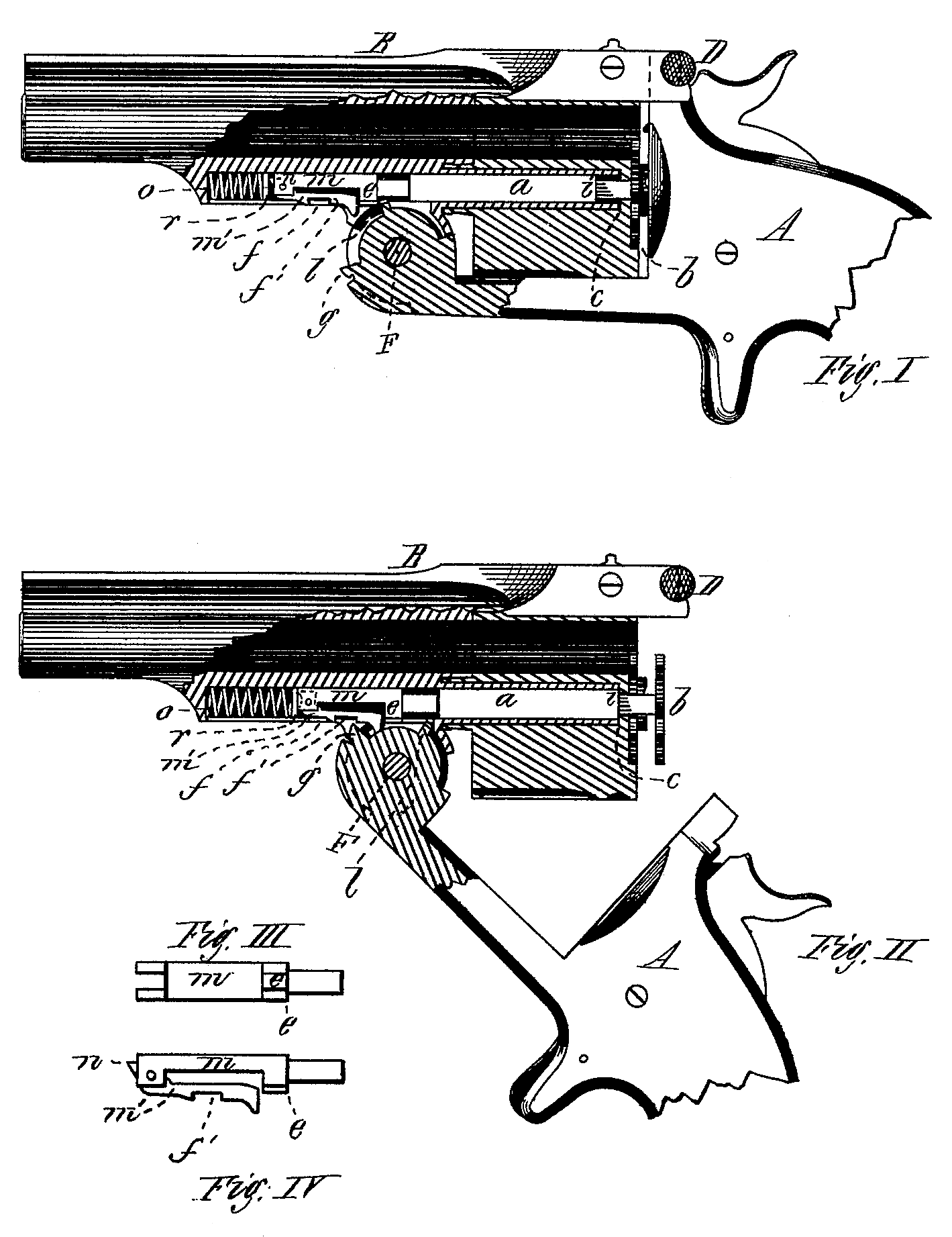
Figure I is a side view of a revolving fire-arm made according to my invention, with a portion broken away, showing the several parts in position and the barrel locked to the frame. Fig. II is a similar view with the barrel unlocked from the frame, and the latter and the recoil-plate moved down and away from the rear end of the cylinder, and the ejector forced outward as in ejecting the shells. Fig. III is a reverse plan or bottom view of the bolt; and Fig.IV is a side view of the bolt and its latch, both the last figures made somewhat enlarged to show their construction.
In the drawings, A represents the frame, B the barrel, and C the cylinder, of a revolving fire-arm, the said cylinder being provided with an ejector-plate, b, of the ordinary kind used with many-chambered cylinders, and having a stem, a, extending into and through the cylinder, said stem having a shoulder at i, and the hole through the cylinder also having a shoulder at c, to limit the movement of the ejector-plate and stem.
Within a recess beneath the barrel is placed a spring, o, with a small disk or plate, r, in rear of said spring, and behind this plate or disk is placed a sliding bolt, m, with a latch, m, pivoted in its forward end. This latch has a point, n, projecting beyond the forward end of the bolt, and the latch has also a recess or gain, f’, made in its lower side.
The joint where the barrel swings in the frame at F is provided with a cam, l, projecting therefrom, and also another at g, on its forward and lower edge; and the bolt m is also provided with a shoulder, e, in rear of which the bolt is somewhat reduced in diameter, as shown clearly in Figs. I and II; and the frame beneath the latch, when the latter is forward in its place, is provided with a catch or bar, f.
The operation of my invention is as follows: When the cartridges are inserted into the chambers of the cylinder, and the frame is tilted up to lock the barrel thereto, the cam l strikes against the shoulder e of the bolt, and the latter, with its latch, is forced forward, compressing the spring 0, the latter and the disk r pressing against the point in, and forcing the latch downward until it catches against the bar f by its recess f’. The bolt is then fastened, so that it cannot pass toward the rear and against the ejector-stem. If the cartridges are then exploded, and it is desired to eject the shells, the latch. D is raised, or the barrel unlocked from the frame, and as the latter is forced down the projection or cam l is forced against the for Ward end of the stem a, and the latter forced back slightly, just sufficiently to start the shells from the chambers of the cylinder. As the former continues its downward movement, however, the cam l moves so far backward and downward that it loses its contact with the end of the ejector-stem, and the latter stops its rearward movement. As the frame is moved still farther downward, the projection g, in passing up, strikes against the rear end of the latch m’, forcing it up sufficiently to unlatch it from the catch or barf, and the bolt is quickly forced back by the spring o, causing it to strike a Smart blow against the ejector-stem, forcing the ejector back quickly, and throwing all the shells entirely out of the chambers, the ejector-stem and bolt being then in position shown in Fig. II. Cartridges may then be partially inserted into the chambers, and as the frame and recoil-plate is moved up again in rear of the cylinder, the cam l strikes against the shoulder e of the bolt, as before, forcing that forward and latching it, the ejector plate and cartridges being forced in by the pressure of the recoil-plate against them. By this quick movement of the ejector and bolt I am enabled to eject the shells from the chambers and throw them entirely out and free from the cylinder without the least trouble.
Having thus described my invention, what I claim as new is—
1. In combination with the hinged joint F, the extractor or ejector stem a, bolt m, with its latch m’, and spring o, all substantially as described.
2. In combination with the bolt on and its latch m’, the spring o, for operating both the latch and the bolt, substantially as described.
DEXTER SMITH.
Witnesses:
T. A. Curtis,
C. E. Buckland.