
US 198228
UNITED STATES PATENT OFFICE.
DANIEL B. WESSON AND JAMES H. BULLARD, OF SPRINGFIELD, MASS.: SAID BULLARD ASSIGNOR TO SAID WESSON.
IMPROVEMENT IN REVOLVING FIRE-ARMS.
Specification forming part of Letters Patent No. 198,228, dated December 18, 1877; application filed August 3, 1877.
To all whom it may concern:
Be it known that we, Daniel B. Wesson And James H. Bullard, both of Springfield, in the State of Massachusetts, have invented a new and useful Improvement in Fire-Arms; and that the following is a full, clear, and exact description thereof, reference being had to the accompanying drawings, making a part of this specification, and to the letters of reference marked thereon.
One part of our invention relates particularly to revolving fire-arms, while the other part is equally well adapted to be used in revolving or other fire-arms of any and every description, the object of the invention being to cause the cylinder of a revolving fire-arm to be automatically stopped, and held or locked in a stationary position when the hammer is left in its normal position, while the cylinder is left free to revolve when the hammer is held in another position, and also to cause the hammer to rebound after having struck the firing pin or the shell, to explode the cartridge.
Our invention consists, first, of a cylinder stop, combined and arranged with the tumbler, and with the trigger provided with a cam, so that by the impingement of the cam against the tumbler at the desired point the movement of the cylinder-stop is so controlled as to be prevented from being disengaged from the cylinder, and the latter unlocked while the point of the trigger is in the half-cock notch; and it consists, also, of a stirrup suspended in the loop of the mainspring and pivoted to the rear side of the tumbler, and arranged to have a bearing against the tumbler in the same direction as the line of its movement, either above or below the pivot which secures the stirrup to the tumbler, whereby, when the hammer, in its forward movement, reaches the point to which it is to rebound, the stirrup be comes rigid with the hammer and tumbler, and moves with it, and causes the hammer to rebound, as will be more fully hereinafter described.
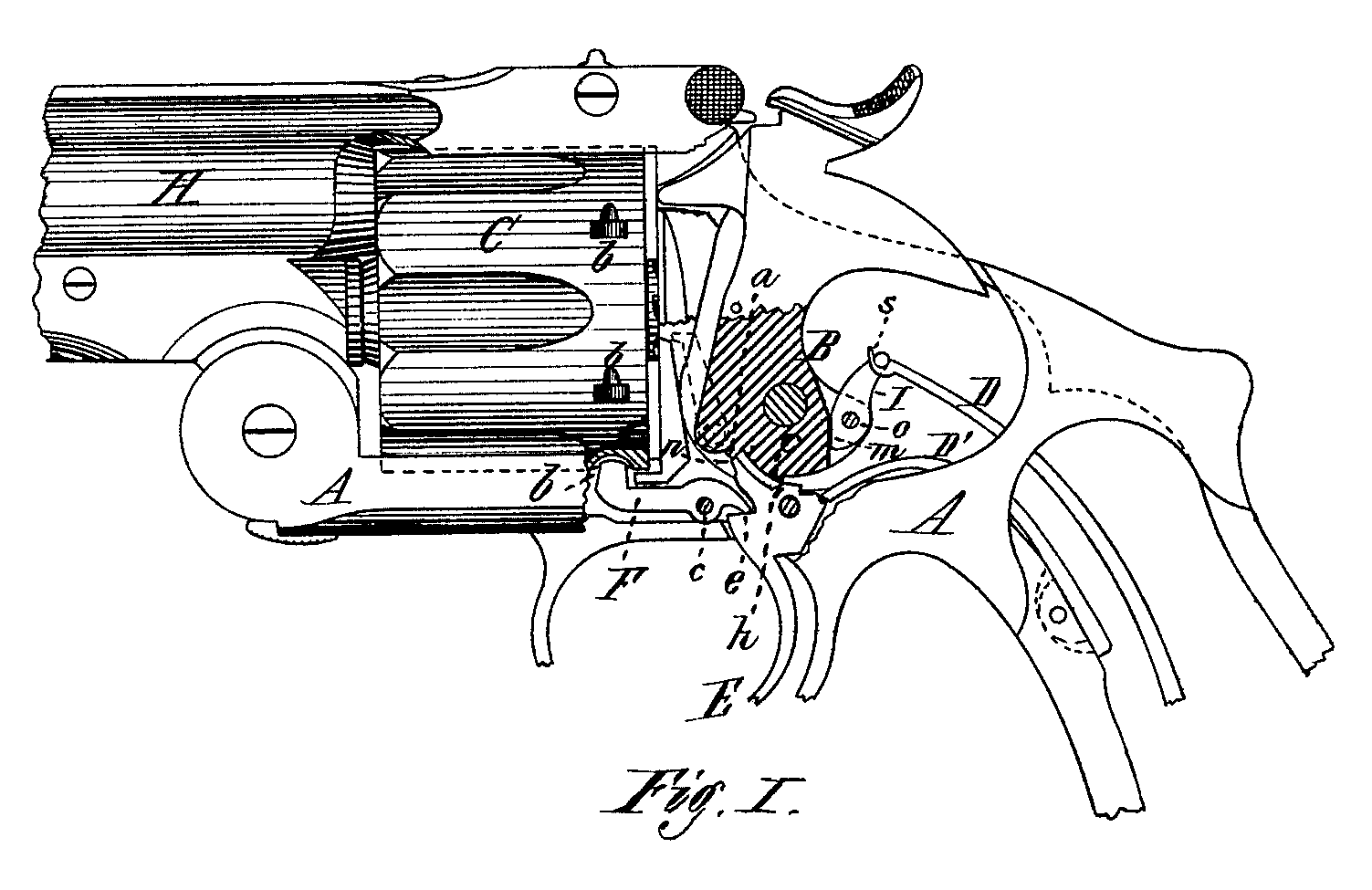
Figure I is a side view of a revolving fire-arm having our invention applied, with a portion of the same in longitudinal section, showing the details of the mechanism.
In the drawing, A represents the frame, H the barrel, and C the cylinder of a revolving fire-arm, with the recesses b made in the cylinder, in which the end of the stop enters, to lock the cylinder in a stationary position. B is the tumbler, pivoted in the frame, the up per part of which serves as the hammer, and is made in one solid piece with the tumbler; and the latter is provided with the shoulders or projections a and c, ordinarily called notches, against which the point of the trigger engages in the operation of discharging the arm. E is the trigger, pivoted, as usual, in the frame, in the forward part of which is a recess, e, to receive the rear end of the cylinder-stop F, also pivoted in the frame in front of the trigger, the forward end of the stop projecting upward, and arranged to enter the recesses b in the cylinder, The forward upper part of the trigger terminates in a point, n, which, when the hammer is pulled back, engages with the shoulder.c, but which, when the hammer stands at the position of rebound, engages with the shoulder a, as shown in the drawing. Upon the upper part of the trigger E is made a small projection or cam, h, which, when the hammer is down, as shown in the drawing, impinges against the extreme outer part of the projection or shoulder c. To the rear part of the tumbler B, at o, is pivoted the stirrup I, the upper end of which is hung in the loop at the forward end of the main spring D in the ordinary manner.
The rear edge of the tumbler, in front of the stirrup, is made of any desired form, whether curved or straight, but in such manner that when the hammer, in its forward movement, reaches the point to which it is to rebound, the rear edge of the tumbler, in front of the stirrup, will strike against the front edge of the stirrup at some point below the pivot o.
The operation of our invention is as follows: In its position of rebound the hammer stands with the point in of the trigger just behind the shoulder a, and nearly at its outer extremity, the protuberance or cam h on the upper part of the trigger bearing against the shoulder c, and preventing the point of the trigger from passing in the entire depth of the shoulder a. When in this position the rear end of the cylinder-stop F bears against the lower side of the recess e in the forward part of the trigger, and the forward end of the stop projects a little into one of the holes b in the cylinder, and prevents the latter from revolving, or holds it in a stationary position. If, however, the hammer be pulled back slightly, or the lower part of the tumbler B is rotated forward a little, so that the shoulder c will pass just in front of the cam h, to permit the point n of the trigger to pass back the entire depth of the shoulder a, the lower edge of the recess e in the trigger will bear up against the rear end of the stop F, and force its forward end down and entirely out of the recess b in the cylinder; and the latter may then be rotated freely.
As the hammer continues its backward movement, as in the act of cocking it, the point in of the trigger is carried forward and downward again, and the forward end of the stop is thereby permitted to enter one of the recesses b, and stop the motion of the cylinder; and the stop continues to be forced into this recess as long as the forward part of the trigger is thrown forward by this rotating movement of the tumbler; and when the point n of the trigger is engaged with the shoulder c of the tumbler, or is in the cock-notch, and the hammer is cocked, the cylinder remains locked, and is not permitted to revolve again until the hammer is let forward, or the tumbler is rotated backward again, so that the point in of the trigger can pass back the entire depth of the shoulder a.
When the hammer is cocked and the point n of the trigger is against the shoulder c or cock-notch of the tumbler, if the trigger is pulled, as in the act of discharging the arm, the hammer is quickly thrown forward by the force exerted upward upon the rear part of the tumbler B, by the mainspring D and stirrup I, and the hammer flies forward to explode the shell into a position with the shoulder a, just in rear of the extreme point in of the trigger, the said shoulder moving back a little past the point of the trigger.
After striking the shell the hammer instantly rebounds to a position with the shoulder a, just in front of the trigger-point in, this rebounding movement of the hammer being accomplished by the drawing back of the upper end of the stirrup (and of the hammer also, which is then rigid with the stirrup) by the main spring, so that, if the trigger be released from the finger-pressure, its point in will move in a little from the outer end of the shoulder (t, and With the calm h bearing against the shoulder c.
It will be seen from the above description that, if the trigger is pulled when the hammer is cocked, as the hammer flies forward, the stirrup I, as it moves upward, has also a rotary movement upon its pivot o in the tumbler; but when the hammer, in its forward movement, reaches the point to which it is to rebound, or to the position with the point n of the trigger, in the same plane with the shoulder a, the front edge of the stirrup comes into contact with, and bears against the rear edge of the tumbler, at a point below the pivot o, this bearing being in the same direction as the line of movement of the tumbler. The stirrup is thereby prevented from rotating upon its pivot o, and, during the remaining forward movement of the hammer, the stirrup be comes rigid with, and substantially a solid part of, the hammer, and moves with it, losing its own independent movement, and the upper end of the stirrup rides forward and upward a little out of the loop at the forward end of the mainspring, until the shell is struck and the cartridge exploded, when the elastic force of the mainspring draws the stirrup back again until its hook, at the upper end, has a firm bearing in the loop of the mainspring, the hammer being also drawn back, as before described.
As thus arranged the arm is absolutely free from all liability of accidental or premature discharge by careless handling, as it can, in no case, be discharged without pulling the trigger for that purpose when the hammer is cocked, and the cylinder cannot be rotated to bring a cartridge into line with the barrel Without pulling back the hammer for that particularly purpose.
It is evident that the stirrup may be pivoted at its lower end to the tumbler, and a shoulder made upon the latter, just behind the stirrup, and above its pivot o, against which the stirrup would come in contact, and have a bearing. The stirrup and tumbler would operate in precisely the same way, without any change of construction in the parts, the only change being a change of location of the pivot o, and point of contact of the edge of the stirrup with the edge of the tumbler.
Having thus described our invention, what we claim as new is—
1. In a revolving fire-arm, the trigger E, provided with the cam h, in combination with the tumbler B and the cylinder-stop F, whereby the latter is prevented from being disengaged from the cylinder, and the latter unlocked while the point of the trigger is in the safety or half-cock notch, substantially as described.
2. The stirrup I, suspended, at its upper end, in the loop of the mainspring, and pivoted to the rear side of the tumbler, and having a bearing against the said tumbler in the direction of the line of its movement, substantially as and for the purpose herein set forth.
DANIEL B. WESSON.
JAMES H. BULLARD.
Witnesses:
T. A. Curtis,
C. E. Buckland.