
US 193836
UNITED STATES PATENT OFFICE.
DEXTER SMITH, OF SPRING-FIELD, MASSACHUSETTS, ASSIGNOR TO DANIEL B. WESSON, OF SAME PLACE.
IMPROVEMENT IN REVOLVING FIRE-ARMS.
Specification forming part of Letters Patent No. 193,836, dated August 7, 1877; application filed June 12, 1877.
To all whom it may concern:
Be it known that I, Dexter Smith, of Springfield, in the State of Massachusetts, have invented a new and useful Improvement in Fire-Arms; and that the following is a full, clear, and exact description thereof, reference being had to the accompanying drawings, making a part of this specification, and to the letters of reference marked thereon.
My invention relates to that part of the arm which operates to extract the shell after the cartridge has been exploded.
It consists of an extractor-stem, operating in connection with a fixed projection, and a sliding piece, which latter has a forward movement independent of the extractor-stem, by which movement the sliding piece is caused to engage. With the fixed projection, and, by tilting either the barrel or the frame, to extract the empty shell from the chamber, the nature and character of the invention being more fully hereinafter described.
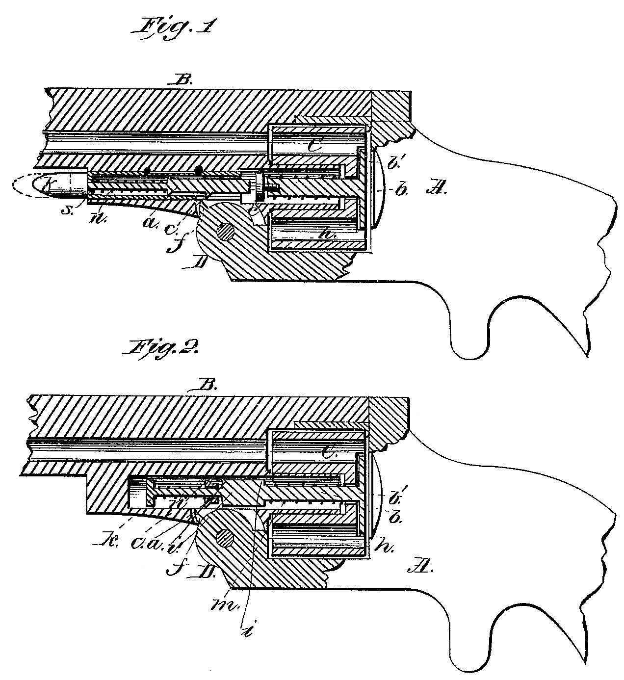
Figure 1 represents one modification of my invention, and Fig. 2 represents another modification of the same.
In the drawings, A represents the frame of a revolving fire-arm, to which my invention is applicable. B represents the barrel, and C the chambered cylinder, arranged to revolve on the tubular pivot or base pin h, fixed to the arm just beneath the barrel B, and the extractor-stem b extends into this tubular pivot or base pin, in the usual manner.
A recess is made in the arm in front of the base-pin h, and, as arranged in the modification shown in Fig. 1, into this recess is fitted a tube, s, to slide to and fro therein, with a spline therein, and a pin inserted, or other convenient arrangement for limiting the sliding movement of the tube.
A rod or sliding piece, a, is inserted into this tube, with a spring, n, Wound upon the forward and smaller part, said spring bearing, at its rear end, against a shoulder or projection on the sliding piece, and at its forward end against a shoulder in the forward end of the tubes, the end of the piece a projecting through the forward end of the tube, and having a button or knob, k, secured thereto.
In Fig. 1 a small projection, c, is made upon the sliding piece a, which, when the barrel is locked to the frame, stands just in front of the fixed projection f on the joint D.
The extractor and its stem b, and their arrangement within the cylinder with the actuating-spring in, are the same as ordinarily used. In Fig. 1 the extractor-stem b is made somewhat short, or of about the same length as the cylinder, with a screw, e, turned into the end of the stem, to serve as a shoulder for the end of the spring on to bear against, and the sliding piece a is directly in front of this screw.
As arranged in Fig. 1, the operation of my invention is as follows: With the parts all in place, as shown in the drawings, if the frame A be held stationary, and the forward end of the barrel be tilted down, the small projection c upon the sliding piece a comes into contact with the fixed projection f on the joint D on the frame part of the arm; and while this tilting movement continues the sliding piece is pushed back and upward against the extractor-stem and screw e, forcing the extractor back and removing the shells. During the latter part of this backward movement the sliding piece a, moving in a straight line while being carried around the joint, finally moves so far away from the fixed projection f that the latter loses contact With the point c, and the extractor and stem b are quickly carried back into the cylinder, and the sliding piece a and the tube s (which has moved with the sliding piece) back into their original position in their recess. As the forward end of the barrel is then tilted up to lock the barrel to the frame, the point c is then in front of the fixed projection f, instead of behind it, as at first, and as the barrel moves up, the point c comes in contact with the front side of the projection f, and the sliding piece is carried forward to the position shown in dotted lines in Fig. 1, or until the point c is carried forward so far as to lose contact with the projection f, when the spring a carries the sliding piece a quickly backward, with the point c behind the projection f, or into the original position shown in Fig. 1.
The same mechanical equivalents, with the same principle of operation, are shown in Fig. 2, in which b is the extractor-stem, enlarged about midway to form a shoulder at i for a bearing, for the spring m, and with a shoulder at i’, against which the sliding piece a strikes.
The extractor-stem b is made longer than that shown in Fig. 1, and extends forward in to the recess beneath the barrel, that part of it forward of the shoulder i’ being made Smaller, and the sliding piece a in Fig. 2 is made in the form of an annular collar, and slides freely to and fro on the small part of the stem, a spring, n, placed upon this part of the stem, and bearing at its forward end against a knob or button, k, secured to the end of the stem, or made thereon, operating to keep the collar or sliding piece a back against the shoulder i’.
The operation in this modification is precisely similar to that already hereinbefore described— that is to say, as the barrel B is tilted down, the fixed projection f comes in contact with the front side of the point, c, which, in this case, is made annular, and the extractor-stem and the sliding piece a are carried back and upward until the annular point closes its contact with the projection f, and the spring on forces the stem and sliding piece a quickly back into their original position, the projection f being then in the rear of the sliding piece a. As the barrel is then tilted upward again the projection c on the sliding piece comes in contact with the front side of the projection f, and the sliding piece is carried forward until it loses contact with the projection, when it is forced quickly to the rear side of the latter by the spring n into its original position, as shown in Fig. 2.
It is evident that this invention is equally well adapted to be used upon all fire-arms in which the barrel is pivoted to and tilts upon a frame or breech, and the extractor can be arranged to remove one or more shells, according to the nature of the arm, without departing from the principle of operation, as above described.
Having thus described my invention, what I claim as new is—
In an automatic extractor for fire-arms, the combination of a fixed projection with a sliding piece arranged in connection, with the extractor-stem, said sliding piece having a backward movement; when engaged; with the fixed projection to. extract, the shells, and, having also a movement forward independent of the extractor, to enable it to engage with the fixed projection, and place itself in position to extract the shells, substantially as described.
DEXTER SMITH.
Witnesses:
T. A. Curtis,
E. A. Thayer.