
US 194653
UNITED STATES PATENT OFFICE.
JAMES A. CROCKER, OF PROVIDENCE, RHODE ISLAND.
IMPROVEMENT IN REVOLVING FIRE-ARMS.
Specification forming part of Letters Patent No. 194,658, dated August 28, 1877; application filed May 29, 1877.
To all whom it may concern:
Be it known that I, James A. Crocker, of Providence, in the county of Providence and State of Rhode Island, have invented a new and useful Improvement in Breech-Loading Guns, of which the following is a specification:
The nature of my invention consists in combining with a double-barreled gun revolving charge-chambers, said chambers being so arranged and connected with guard and intermediate operating mechanism, that a single movement of the guard brings a new pair of charge-chambers in line with the pair of barrels.
My invention also consists in certain details of construction, which may be best understood by reference to the drawings.
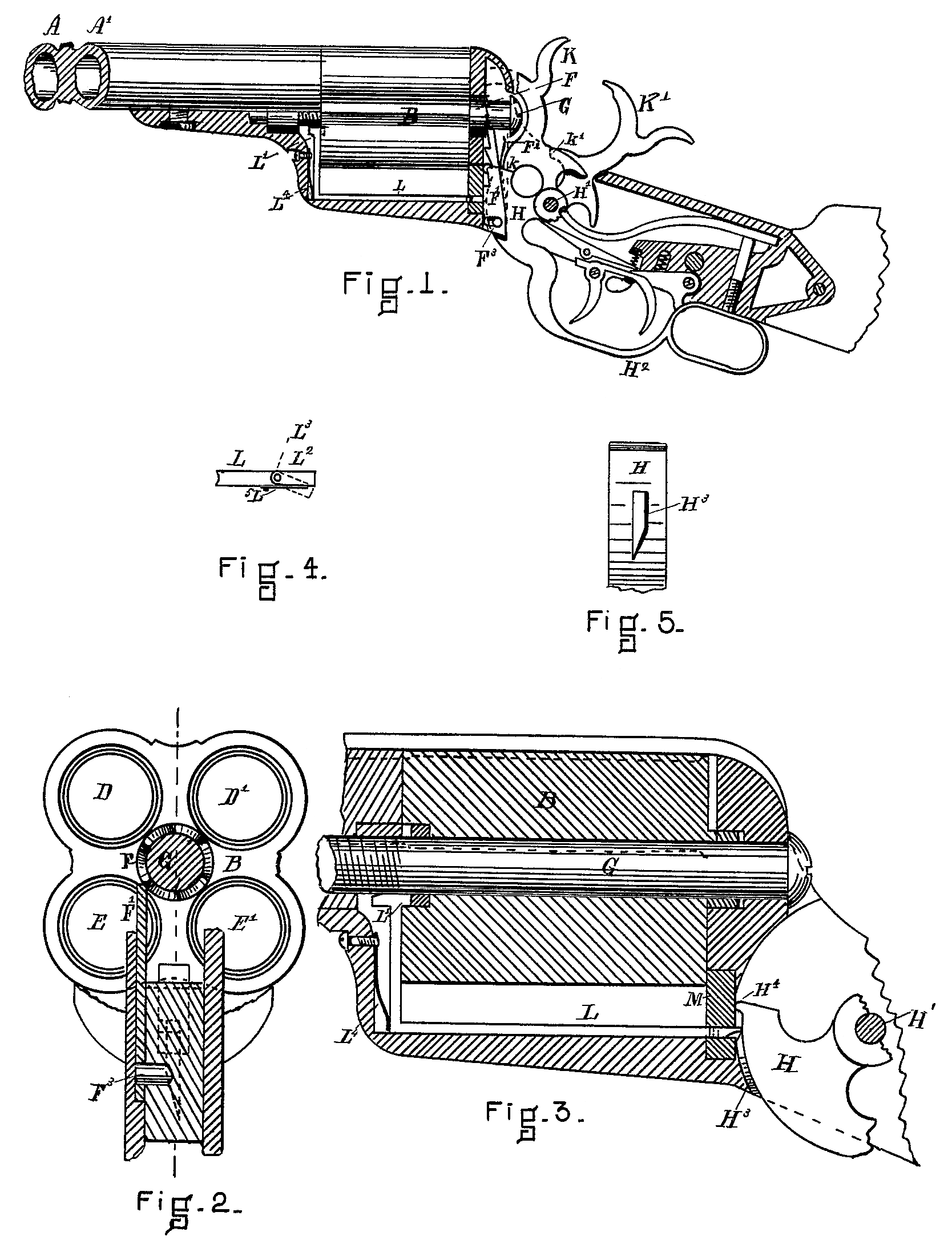
Figure 1 is a view showing the barrels and charge-chamber in elevation, also the other parts it section and elevation. Fig. 2 is a view showing the rear end of the charge chambers, the crown-ratchet and pawl for revolving the saline, also part of the guard and clamping device. Fig. 3 is a vertical longitudinal section through the charge-chamber and adjacent parts. Figs. 4 and 5 are details relating to the chamber-locking device.
A A’, Fig. 1, represent two barrels of a double-barreled gun or pistol. These, together with the stock, triggers, and hammers, may be made in any desired style and manner, and need not be further described.
The charge-chambers D D’ E E’, Fig. 2, are formed in the revolving block B, Figs. 1, 2, and 3. This revolving block is hung on the spindle G, and has attached to its rear end a crown-ratchet, H H^2 His the guard, which is hung on a pivot, H^1, in common with the two hammers K K’. This guard when thrown out throws up the pawl F^1, which is connected to it by the pin F^3, and thus acting on the crown-ratchet F causes the charge-chamber block B to revolve through one half-revolution, the pawl F^1 being held against the ratchet by the spring F^2, Fig. 1. This movement of the guard also serves to cock the hammers, which it does by coming in contact with the shoulders k k’, Fig. 1, of the hammers, and thus forcing them back.
L L’, Figs. 1 and 3, is a bent rod, which serves to lock the charge-chamber block B, the point L’1 entering a recess made in the block B. This rod is thrown so as to engage with the recess by the spring L^4, which is disengaged from the block B by a switch-cam, H^3, Figs. 5 and 3, formed in the guard H, which acts in the following manner: The bent rod L terminates in a swinging switch, L^2, pivoted to it at L, and held in line by a spring, L^5, Fig. 4, so that when the guard H H^2 is thrown down, the switch-cam H^3 comes in contact with LP, and forces L and L^1 forward, so that the point L^1 is disengaged from the charge-chamber block B, thus leaving the block free to be revolved by the pawl F^1. But when the guard H H^2 is brought back the point of the switch-cam H^3 throws the switch L^2 aside, and thus fails to act on the locking device L L^1.
M, Fig. 3, is a friction block placed at the end of the charge-chamber block B, and is pressed upon by a point, H^4, of the guard H H^2, when said guard is in normal position. As soon as the guard is moved in the slightest, the point H^4 frees M. from pressure, and thus leaves the block free. The function of this friction-block M is to force the charge-chamber block B hard up against the ends of the barrels, and thus prevent escape of gas.
Having now described the construction and operation of my invention, what I desire to secure by Letters Patent is—
1. The combination of the double barrel A A’, and the charge-chamber B, with the crown-ratchet F, the pawl F^1, and the guard H H^2, all operating together, substantially as described, and for the purpose set forth.
2. The combination of the charge-chamber B, the bent rod L L^1, and the guard H H^2, provided with the cam H^3, substantially as described, and for the purpose set forth.
3. The combination of the charge chamber B and the friction-block M with the point H^4 on guard H H^4, all operating together, substantially as described, and for the purpose set forth.
JAMES A. CROCKER.
Witnesses:
William Edson,
Nathl. Evans.