
US 176448
UNITED STATES PATENT OFFICE.
DEXTER SMITH AND JOSEPH C. MARSHALL, OF SPRINGFIELD, MASSACHUSETTS.
IMPROVEMENT IN REVOLVING FIRE-ARMS.
Specifications forming Letter Patent No, 176,448, dated April 25, 1876; application filed March 4, 1876.
To all whom it may concern:
Be it known that we, Dexter Smith and Joseph C. Marshall of Springfield, in the State of Massachusetts, have invented a new and useful Improvement, in Revolving Fire-Arms; and that the following is a full clear, and exact description thereof, reference being had to the accompanying drawing, making a part of this specification, and to the letters of reference marked thereon.
The object of our invention is to provide an extractor for a revolving fire-arm, which may be operated to extract shells by ordinary operation of discharging the arm. To this end our invention consists of an extractor pivoted to the hammer, or to a piece connected to an moving in the same direction as the hammer, and actuated by the latter, said extractor vibrating upon its pivot, and which, in extracting a shell approaches the – latter from the rear and inserting its point in front of or beneath, the flange, of the shell, being guided by a spring, and operating as a wedge to start the shell from the chamber, and as a lever to eject it, and having a cam or protuberance upon its front edge, which strikes against the frame to give the extractor an accelerated backward movements, to eject the shell, all which will be more fully hereinafter described.
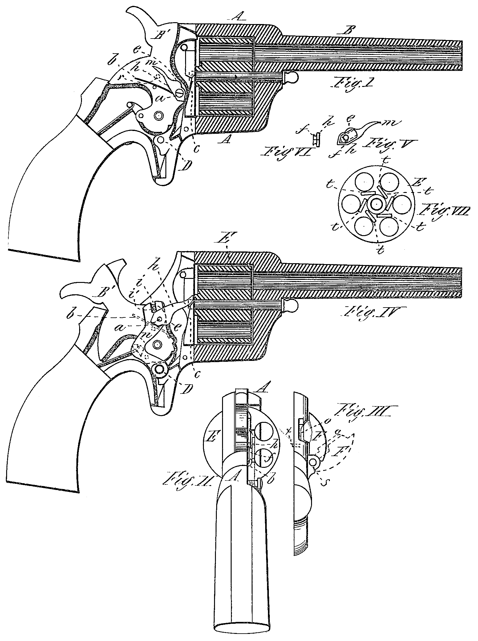
Figure I is a sectional view of the barrel, cylinder, and part of the frame of a revolver having our invention applied, and with part of the frame or the side plate removed to show the extractor attached to the hammer. Fig. II is a rear view of the arm with the side plate removed. Fig. III is a rear end view of the side plate, showing the gate pivoted thereto, which, when shut in rear of the cylinder, prevents the extractor from extracting the shells. Fig. IV is a sectional view of the barrel, cylinder, and part of the frame, with the side plate or part of the frame removed, showing the extractor as attached to a vibrating piece connected to and operated by the hammer. Fig. W is a reverse side view of the extractor, showing the projection on the inside, against which the guiding-spring presses to guide the point of the extractor beneath the flange of the shell. Fig. VI is a rear end view of the same, and Fig. VII is a rear end view of the cylinder, showing the groove ar the side of each chamber, into which the point of the extractor enters in extracting the shell.
In the drawing, A represents the frame, B the barrel, and E the cylinder of any ordinary revolver, and B’ the hammer, pivoted in the frame in the usual manner. To the side of the hammer at a is pivoted and extractor, h, having a pointed finger, m, and upon the side next the hammer a projection, f, or elongated cam, made more or less pointed or the lower end, as shown clearly in Fig. V, an whit a protuberance, e, on the front edge.
A spring, b, is so arranged upon the side of the hammer that one end of it presses; against one side or the other: of the projection f, according as the extractor is, tilted forward or back, to guide the extractor in its movements, and a pin or projection, x, is placed on the inside of the side plate, against; which the extractor strikes when it; moves back with the hammer, as will be explained hereafter the position of the pin when the side plate is in place being, as show, dotted in at r in Fig. I.
The operation of our invention is as follows: Suppose there are cartridges in all the chambers, and one has been exploded. When the hammer is cocked the cylinder is rotated bringing the next cartridge into position, and in the movement of the hammer backward, the extractor h (which is in the position shown in Fig. I) strikes against the projection x and is tilted forward into the position shown in Fig. IV, and is held in that position by the spring b, which presses up against the lower side of the projection f on the extractor.
As the hammer moves forward in exploding the next cartridge the point of the extractor, being held by the spring in the proper position, is guided into and enters the small groove t, made at the side of each chamber. As the flange or head of the cartridge is just in the rear of this groove the point of the extractor, as it enters, the groove, operates as a wedge to force back the cartridge, and, as the small end of the extractor is slightly curved, as the hammer moves down against its cartridge, the bottom of the groove t guides the point of the extractor upward, tilting the extractor into a nearly-vertical position, forcing out the shell still farther until it is perfectly loosened from the chamber, when the protuberance e on the front edge of the extractor strikes against the part c of the frame, which throws the point of the extractor quickly backward, giving the said extractor a sudden accelerated movement backward, and ejecting the shell entirely from , the chamber. When the extractor is thus thrown or tilted backward, the lower end of the projection f tilts over upon the spring b until the latter presses against the opposite side of the said projection, and the hammer is then moved back, as before, the extractor striking against the projection x, to tilt it forward again, as before.
A gate, F, is pivoted at s to the frame or side plate in rear of the cylinder, which gate is provided with a plane projection, o, which, in Fig. III is just, in the rear of the cartridge-head and in front of the extractor, so that, when shut, the gate prevents the point of the extractor from passing in under the cartridge, the point of the extractor striking the said projection o in its forward movement, and being caused to tilt and operate the same as if the shells were being extracted.
The arm may thus be discharged, and the shells extracted at each discharge, by opening the gate F, as shown in dotted lines in Fig. III, or be discharged without drawing the shells, by shutting the gate, as shown in black lines in the same figure.
Instead of being pivoted to the hammer, the extractor may be pivoted to another piece, swinging behind the hammer-pivot in the same direction as the hammer, and operated by it, as shown clearly in Fig. IV, in which n is a cooked piece swinging behind the hammer-pivot, and hung upon the trigger-pivot D, said piece having a recess, i, which engages with a pin, i, in the hammer. In this case the spring b may be arranged on the frame, inside, or on the side plate, but in the same position as upon the hammer in Fig. I, as shown in dotted lines in Fig. IV, so that whatever the extractor is attached or pivoted to, as it vibrates back and forward, its movements and operations are precisely alike.
It will be seen that when the hammer is at half-cock the ejector is held in a position tilted back by the spring, so that the point of the ejector is out of the way when loading the arm, and is held in a position tilted forward, ready for extracting the shell when the hammer is at full cock, the extractor being tilted or thrown forward by contact with the projection x when the hammer is moved back to a full cock.
Having described our invention, what we claim as new is—
1. In a revolving fire-arm, the ejector k, swinging upon a movable pivot, and arranged to be forced under the rim of the cartridge-case, starting and ejecting the same from the rear end of the cylinder by an accelerated backward movement, substantially as described.
2. In combination with a cartridge-shell ejector, the grooves or recesses t, made in the rear face of the cylinder, for the purpose of guiding the said ejector under the head of the shell, substantially as set forth.
3. The combination of the hammer, the frame, and the ejector, provided with the protuberance e on its front edge, which strikes against said frame, whereby an accelerated backward movement is imparted to said eject or, all constructed substantially as described.
4. The combination, substantially as herein described, of the ejector h, the spring b, and projection x, whereby the ejector is held back by the spring when the hammer is at half-cock, and thrown forward by said projection into position by raising the hammer to full cock.
5. In combination with an extractor swinging upon a movable pivot, and arranged to insert its end into the grooves t made in the rear ace of the cylinder, a gate, F, pivoted to the frame, against the rear face of which, when shut, the end of the extractor strikes, aid is thereby prevented from entering the said grooves, substantially as and for the purpose set forth.
Dexter Smith,
Joseph. C. Marshall.
Witnesses:
T. A. Curtis,
C. E. Buckland.