
US 175180
UNITED STATES PATENT OFFICE.
TEIOMAS J. SLOAN, OF TUCKAHOE, NEW YORK.
IMPROVEMENT IN REVOLVING FIRE-ARMS.
Specification forming part of Letters Patent No. 175,180, dated March 21, 1876; application filed March 26, 1874.
To all whom it may concern:
Be it known that I, Tomas J. Sloan, of Tuckahoe, in the county of Westchester and State of New York, have invented certain Improvements in Revolving Fire-Arms, of which the following is a specification:
This invention comprises a novel mechanism, whereby in a revolving fire-arm the hammer may be raised to a cocked position by pulling the trigger, supported in a cocked position upon discontinuing the pull upon the trigger, and fired by continuing the pull upon the latter, a very efficient and conveniently-manipulated revolver being thereby produced. The invention further comprises certain novel combinations of parts, whereby the trigger is retained in proper relation to the hammer to retail the same at full cock when the pull upon the trigger is discontinued, whereby the accidental discharge of the arm may be provided against, whereby the facile manipulation of the trigger in cocking and firing is provided for, and whereby the firing-pin attached to the hammer may be withdrawn when occasion requires, all as hereinafter fully set forth.
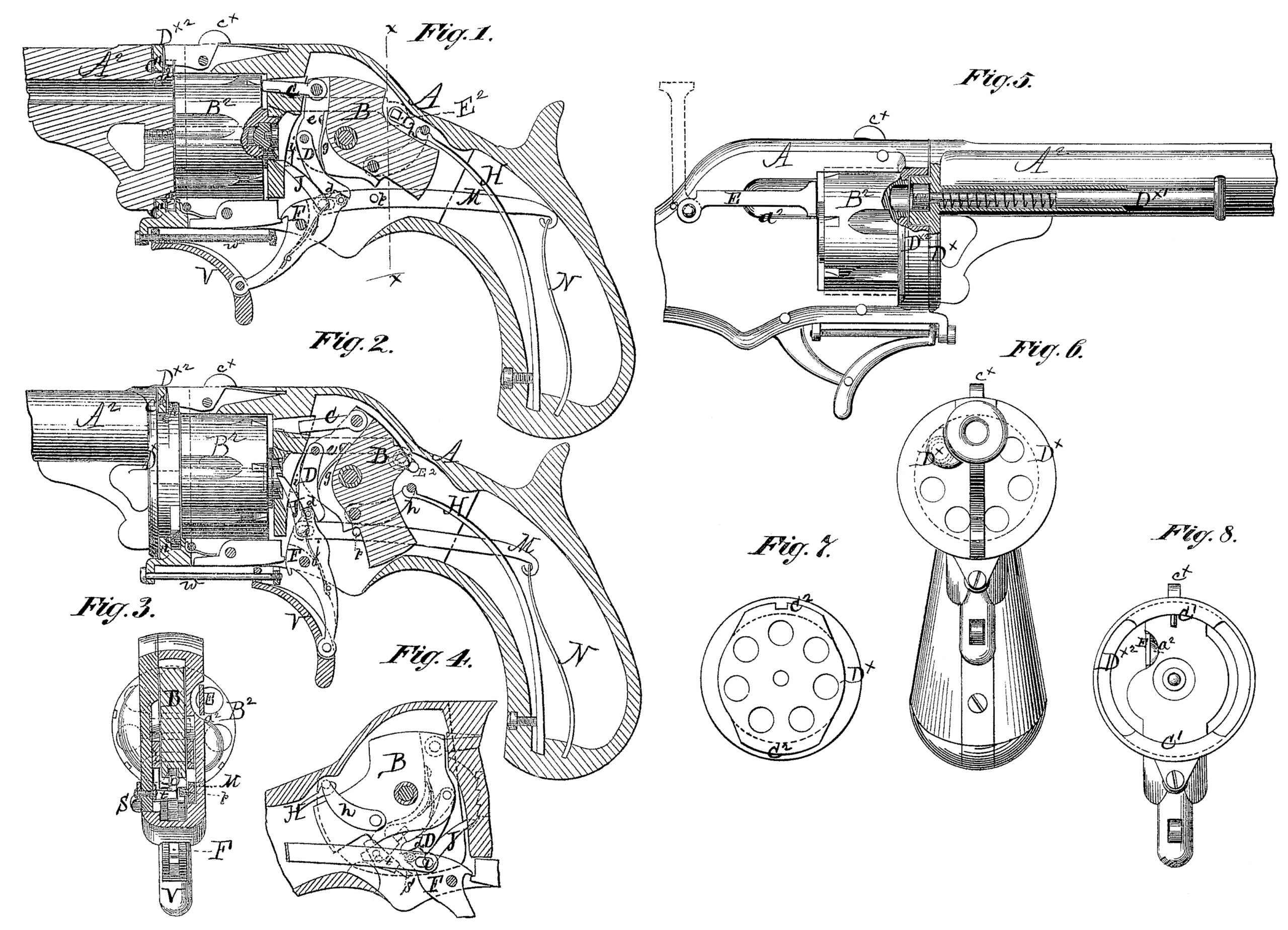
In the accompanying drawing, Figure 1 is a central longitudinal vertical section, showing the hammer down. Fig. 2 is a similar view, showing the hammer cocked. Fig. 3 is a transverse section taken in the line x x of Fig. 1. Fig. 4 is a section showing the breech mechanism on the side opposite to that shown in Figs. 1 and 2. Fig. 5 is a side view, partly in section, on the side opposite to that shown in Figs. 1 and 2. Fig.6 is a front or end view of the same looking from the muzzle toward the stock. Figs. 7 and 8 are face views of the parts carrying the mutilated flanges.
The hammer B is entirely inclosed within the stock A, instead of having a comb projecting upward through a slot for the purpose of cocking the piece with the thumb, as in the usual way.
Instead of a nose on the upper front corner of the hammer for exploding the cartridge, I employ a firing-pin, C, which is pivoted to the hammer, and works in an opening in the recoil-block in rear of the chamber in line with the barrel, and may be adapted to either center-fire or rim-fire cartridges.
In the face or front edge of the hammer is a groove, e, in which is pivoted the upper end of a hanging sear, D, in the lower end of which is a notch, d, for engagement with the upper end of the trigger F. In the bottom of the groove e, behind the sear D, is a spring, g, which has a tendency to press the lower portion of the sear in a forward direction. When the hammer is down the parts are in the positions shown in Fig. 1, with the notch d engaging with the upper end of the trigger. When the trigger is pulled back it operates upon the sear to raise or cock the hammer, and as soon as the sear has passed a vertical line drawn from its pivot it strikes the rear side of the recoil-block, or an abutment, i, thereon, and supports the hammer in a cocked position, as shown in Fig. 2. When the pressure upon the trigger is continued its upper end is released from the notch d, passing under the abutment i, and allowing the sear to pass behind it and the hammer to fall. The mainspring His connected to the hammer by means of a stirrup, h, in the usual manner.
It will be particularly noticed that, as the movement of the sear is stopped or limited by the recoil-shield, all nicety of workmanship that would be required in providing a stop within the trigger itself is dispensed with, and the accurate fitting of the parts in place is rendered easy and convenient.
For revolving the cylinder I employ a pawl, J, which is attached to the trigger F, in rear of the pivot thereof, instead of to the hammer. This pawl has an elbow at its lower end, which forms its pivot, and has one side flattened to form a bearing-surface for a spring, j, which serves to hold it in position. The pawl passes through an aperture in the recoil-block, and its free end engages with the ratchet on the rear side of the cylinder. When the trigger is pulled to cock the hammer, the cylinder is revolved at the same time by means of the pawl.
The trigger F has a pin or stud, l, projecting from the side opposite to that on which the pawl J is attached, which pin engages with a slot near the front end of a rod or bar, M, to the rear end of which is attached a spring, N. This rod and spring take the place of the ordinary trigger-spring. On the side of the bar M nearest the hammer a pin, p, projects laterally, so as to engage with the front edge of the lower portion of the hammer. When the hammer has reached the position of full-cock the front edge of its lower portion is engaged with the pin p, so that the bar M cannot be drawn back by the spring N.
The upper end of the trigger F may be provided with a friction-roller, r, for engagement with the notch in the sear D.
To prevent the accidental discharge of the arm I employ a safety device, consisting of a button or thumb-piece, S, on the outside of the stock or lock-plate, pivoted in said lock-plate, and having on the inner end of its pivot a bar, t, bent inward in a direction parallel with its axis. (See Figs. 3 and 4.) When the thumb-piece S and bar t are inclined downward, as shown in Fig. 3, and in full lines in Fig. 4, the sear D is free to engage with the upper end of the trigger; but when the thumb-piece is turned so as to be inclined slightly upward, as shown in dotted lines in Fig. 4, the bar t engages, with the lower end of the sear D, so as to press it upward and backward, and allow the trigger to be manipulated with out coming in contact with the sear, or affecting the position of the hammer, so that the arm cannot be fired by manipulating the trigger while the bar t is engaged with the sear.
To facilitate the manipulation of the trigger its lower end is pivoted to a finger-piece, V, which is suitably connected with a bar, w, to prevent its displacement.
If desired, the hammer may be lowered without discharging the arm, by moving the trigger forward slowly and carefully, holding it between the first and second fingers, with out changing the position of the hand.
The cylinder B^2 is secured to the barrel A^2 by means of a screw, which forms its pivot.
Instead of being hinged to the stock in the usual way, the barrel and stock are coupled together by means of internal and external multilated flanges C^1C^2, the latter being formed on a plate or disk, D^x, on the rear end of the barrel, and the former on the inner surface of a ring or band, D^x2, attached to the stock. The parts are coupled by placing the disk against the front edge of the ring, with the flanges C^2 about ninety degrees distant from the flanges C^1, and then turning the parts until the flanges engage with each other and the barrel is in line with the central upper portion of the stock, in which position the parts are locked by means of a spring-catch, c^x. On one side of the barrel is an ejector-pin, D^x, working in a sleeve, and surrounded by a spiral spring, for holding it in the position shown in Fig. 5. In rear of the cylinder a recess, a^2, is formed in the side of the stock, to enable the cylinder to be loaded without removing it from the stock. An elastic bar, E, is pivoted to the stock, so that its front end may be made to lie in the recess a^2, and prevent the displacement of the cartridge from the chamber of the cylinder, which may be opposite to the recess a^2. On the inner end of the pivot of the bar E is a lever, E^2, (see Fig. 2.) running in a direction nearly opposite to that of the bar.
When the cylinder is to be loaded, the bar E is raised to the position shown in dotted lines, causing the lever E^2 to bear upon the heel of the hammer B and depress it, so as to withdraw the firing-pin C. The thumb-piece S is moved up, so as to throw the sear D out of engagement with the trigger. The cylinder is then revolved, by means of the trigger and pawl, so as to bring the chambers successively opposite the recess a^2, and allow the cartridges to be inserted.
When the shells are to be extracted, or the cylinder unloaded, the ejector-pin D^x1 is pushed inward through the chambers as they are successively brought opposite to its inner end by the revolution of the cylinder.
What I claim as new, and desire to secure by Letters Patent, is—
1. The hammer, sear, trigger, and recoil block, the whole constructed, combined, and arranged substantially as herein specified, – whereby the hammer is raised to a cocked position by pulling the trigger, supported in a cocked position upon discontinuing the pull upon the trigger, and fired by continuing the pull upon the same, as described.
2. The bar M, constructed with the pin p and the spring N, in combination with the hammer B and trigger F, substantially as specified, whereby the trigger is retained in its proper position relative to the hammer, to retain the latter at full-cock when the pull upon the trigger is discontinued, as described.
3. The pivoted button or thumb-piece S, provided with the bar z, in combination with the pivoted sear D, whereby the latter may be thrown forward out of engagement with the trigger.
4. The finger-piece V, arranged to slide up on the rod w, and pivoted to the lower extremity of the trigger F, the whole combined for operation substantially as specified, where by provision is made for the facile manipulation of the trigger, as described.
5. The bar E and lever E^2, in combination with the hammer B, substantially as set forth, whereby provision is made for the withdrawal of the firing-pill, as described.
TEOS. J. SLOAN.
Witnesses:
Michael Ryan,
Fred. Haynes.