
US 112471
UNITED STATES PATENT OFFICE.
EDWIN. S. LEAYCROFT, OF BROOKLYN, NEW YORK, ASSIGNOR, BY MESNE ASSIGNMENT, TO COLTS PATENT FIRE-ARMS MANUFACTURING COMPANY, OF HARTFORD, CONNECTICUT.
IMPROVEMENT IN REVOLVING FIRE-ARMS.
Specification forming part of Letters Patent No. 112,471, dated March 7, 1871.
To all whom it may concern:
Be it known that I, Edwin. S. Leaycroft, of the city of Brooklyn, in the county of Kings and State of New York, have invented a certain new and useful Improvement in Revolving Fire-Arms; and I do hereby declare the following to be a full, clear, and exact description of the same, reference being had to the accompanying drawings, making part of this specification, and to the letters of reference marked thereon.
My invention relates to revolving-breech fire-arms, having reference to a method of suspending the revolving breech or cylinder in the frame.
It has for its object to provide for the free rotation of the cylinder; and it consists in the combination, with the many-chambered cylinder, of a peculiarly-formed axis-pin, on which the breech is free to turn, and which is itself also free to turn on its axis, and of a removable support for one end of the said pin, constructed, combined, and arranged substantially in the manner hereinafter set forth.
Heretofore the cylinders of revolvers have usually been sustained on fixed axis-pins. This arrangement is objectionable because the rotation of the cylinder is liable to become impeded by powder smoke being forced in between the pin and the cylinder, forming a deposit there, which gradually accumulates and impedes more and more the rotation of the cylinder, until, after comparatively few rounds have been fired, great difficulty is experienced in operating the arm.
To enable others skilled in the art to make and use my invention, I will proceed to describe it.
In the several figures of the drawings similar letters of reference denote the same part.
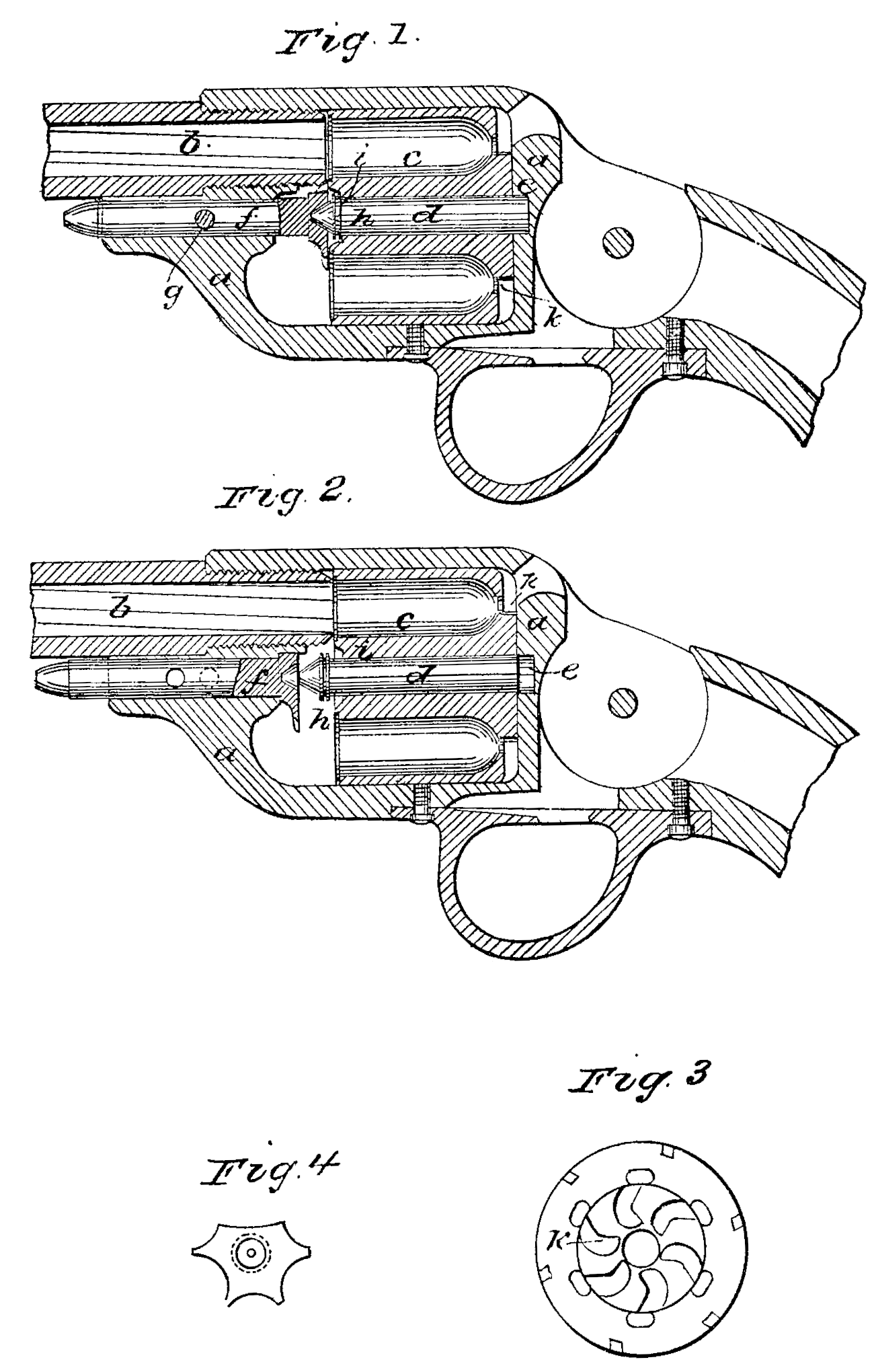
Figure 1 is a longitudinal section of parts of a pistol embodying my improvements. Fig. 2 is a similar view, with the parts in such positions that the cylinder may be removed from the frame. Fig. 3 is an end view of the cylinder, and Fig. 4 an end view of the supporting-bar.
a is the frame of the pistol; b, the barrel; c, the chambered cylinder, the axis of which is parallel with that of the barrel. It is perforated along its axis by a cylindrical hole.
d is the center-pin. Its axis corresponds with that of the breech. This center-pin is longer than the breech. c, its body, is cylindrical, and fits loosely in the central hole of the breech, so that the breech may turn freely thereon. The rear end of the center-pin enters a recess at e in the frame a, while its front end, which is conical, enters a correspondingly-shaped cup in the end of a supporting-bar, f, which is fixed by a transverse pin or key, g, in a socket formed in the frame a, beneath the barrel. When the key g is removed the barf may be slipped forward endwise. The ends of the pin d are so fitted in their supports that the pin is free to turn on its axis.
Near the front end of the pin d is a grooved flange, h, which,when the parts are in the proper position for the use of the pistol, (see Fig. 1) bears against the bottom of a recess, i, formed in the front end of the breech c.
The ratchet k, by which the breech is rotated, surrounds the axis-pin hole, and is arranged in the usual way. (See Fig. 3.) All other parts of the pistol may be constructed and perform their functions in the customary manner.
The operation of my invention is as follows: The flanged part h of the front end of the center-pin d bears against the bottom of the recess i in the breech and acts as a valve; and when the gases of explosion (which escape between the barrel and the breech) are blown forcibly against the end of the breech the flange, covering as it does the joint between the center-pin and breech, is closely pressed against its bearing by the force of the gas, so as to prevent the gas and smoke from entering the joint and from forming an accumulation of soot there. The conical form of the center-pin end and of the cup in which it turns is advantageous as to offering less opportunity for soot to accumulate there. By the jarring of the parts in firing any deposit at that place becomes loosened and works out from the joint.
It will be readily understood that the rotation of the cylinder is with my invention but little likely to become impeded from any cause, for if its turning on the center-pin be prevented then the pin may turn in its supports, and vice versa.
What I claim as my invention, and desire to secure by Letters Patent, is—
The center-pin d, free to turn on its axis, and the movable support f, in combination with a many-chambered cylinder, c, free to turn on the center-pin, all constructed and arranged substantially in the manner hereinbefore specified, for the purpose set forth.
EDWIN. S. LEAYOROFT.
Witnesses:
R. Goodenough, Jr.,
Fred J. Stokes.