
US 114653
UNITED STATES PATENT OFFICE.
WILLIAM C. DODGE, OF WASHINGTON, DISTRICT OF COLUMBIA.
IMPROVEMENT IN BREECH-LOADING FIRE-ARMS.
Specification forming part of Letters Patent No. 114,653, dated May 9, 1871.
To all whom it may concern:
Be it known that I, William. C. Dodge, of Washington, in the county of Washington and District of Columbia, have invented certain Improvements in Breech-Loading Fire-Arms, of which the following is a specification, reference being had to the accompanying drawing.
My invention relates to breech-loading fire-arms of that class in which the breech-piece is stationary and the barrel or chamber is moved to open the breech; and the invention consists, first, in combining with such moving chamber or cylinder a hammer that first ignites the charge and then rebounds, so as to be out of the way in opening and closing the breech; and, second, in a novel means of locking together the tipping-frame or barrel and breech-piece, as hereinafter more fully explained.
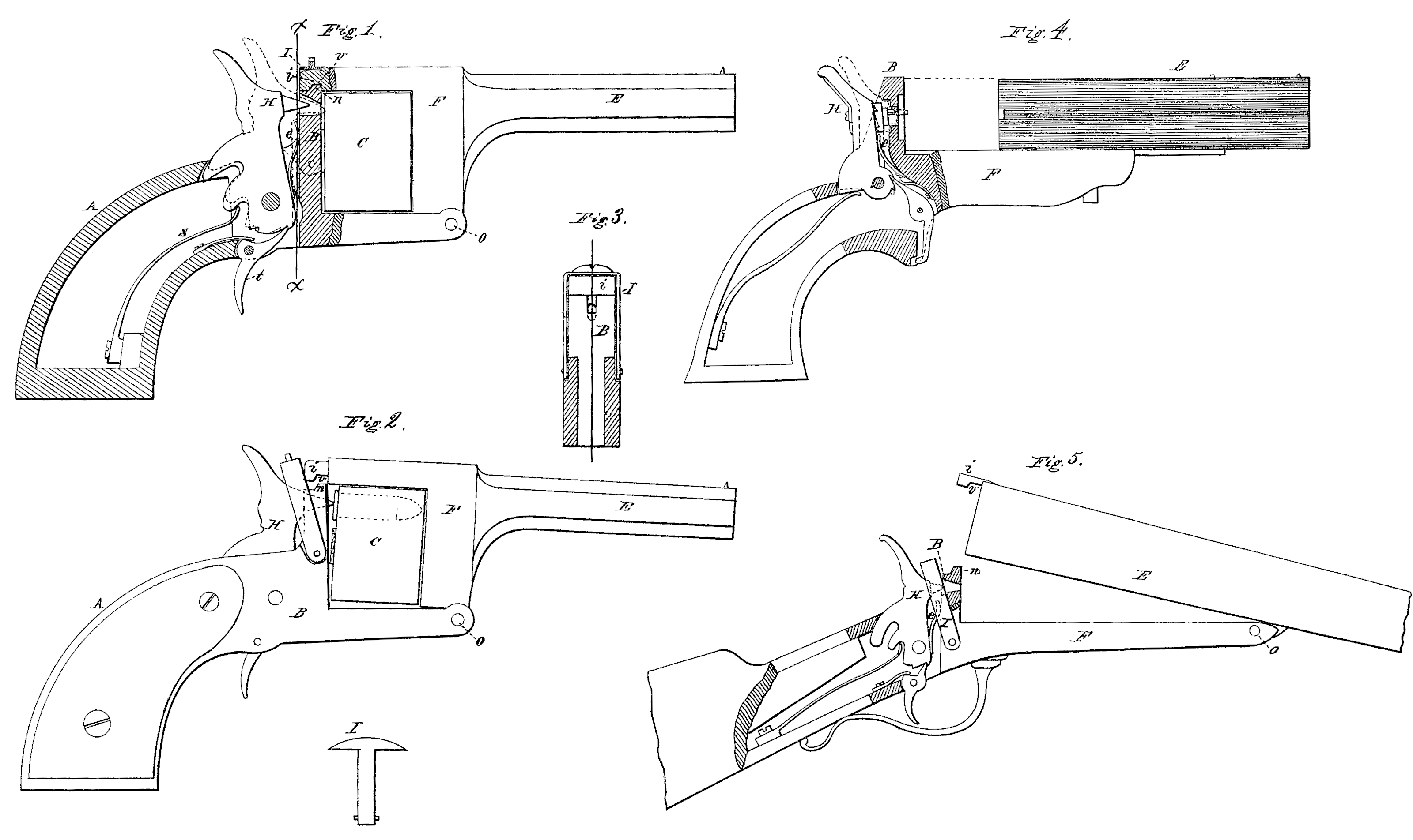
Figure l is a side elevation of a revolver having my improvements applied thereto, a portion being shown in section for the purpose of more clearly illustrating the invention. Fig. 2 is a side elevation of the same, showing the breech in the act of being closed, and illustrating the danger incident thereto when the rebounding hammer is not used. Fig. 3 is a transverse vertical section on the line x x of Fig. 1. Fig. 4 represents an arm in which the barrel slides forward, with a portion of my improvement applied, and Fig.5 represents a rifle or shotgun having my improvements applied.
Since the introduction of metallic cartridges, which contain the entire charge, and have the fulminate arranged to be inline with the point of the hammer, so as to be ignited by a blow therefrom, many arms have been constructed so as to have their barrel or chamber, or the frame to which the cylinder is attached, (if a revolving arm,) either tip or slide forward, in order to open the breech for the insertion and removal of the cartridges, the breech being closed by swinging or sliding the barrel or cylinder back again against the breech-piece, as illustrated in the drawing.
In loading such an arm the barrel or front portion is swung or moved forward, and the loaded cartridges inserted therein from the rear, when the barrel or chamber is swung back into position, bringing its open end with the loaded cartridge against the solid breech.
In the drawing I have shown a revolving fire-arm made on this plan, the cylinder C being connected to the front portion of the frame F, to which also the barrel E is secured, this frame F being hinged or pivoted to the lock frame A at the lower front corner, as indicated at o.
In this class of arms it is desirable to have the point of the hammer H strike through an opening in the recoil or stationary breech-piece B, as shown in the drawing, in order to hit and ignite the charge, thus dispensing with the firing-pin and spring sometimes used, especially in double-barreled guns. With the point of the firing-pin or hammer thus protruding through the breech-piece, it will be seen that, in closing the arm preparatory to firing it, the cartridge in the chamber will inevitably be forced against the protruding point of the hammer, and thereby endanger the premature explosion of the charge, as illustrated in Fig. 2, in which the arm is represented as nearly closed, with the cartridge in contact with the point of the hammer.
In revolvers, and still more in pistols like that represented in Fig. 4, this danger is in creased from the fact that in closing them it is natural to seize the front end of the barrel with one hand, while the handle or stock is held in the other, and then close them with a sudden movement. In such cases the charge is almost certain to be exploded, and if the hand is over the muzzle it is sure to be injured. So, too, in shot-guns and rifles in which the barrel is hinged as represented in Fig. 5 there is a like danger, as it is customary to throw them shut by a sudden motion or jerk, known among sportsmen as the “snap-action.”
Hence, in all this class of arms, if a hammer or firing-pin having its point protruding as represented in the drawing be used, it is necessary always to bring the hammer to a half-cock before closing the breech; and so, too, it is equally necessary to have the hammers at half-cock in order to open the breech or revolve the cylinder, if it be a revolver, and this necessitates another motion by the hand.
To remedy these difficulties I arrange the hammer in such a manner that, when it has ignited the charge, it shall rebound or fly back far enough to bring its point back of the front face of the breech B, as shown in Fig. 1, preferably having it move far enough to have the trigger engage in the first or safety notch, as there shown. This may be accomplished in a variety of ways, that which I prefer being to use the rebounding hammer recently patented to me. It may, however, be accomplished, as represented in the drawing, by placing a Spring, e, in front of the body of the hammer in such a position that, as the hammer swings forward, it will act upon the spring e, which Will, after the hammer has struck the cartridge, force it back to the position shown in Fig. 1. In this position the hammer will remain until it is again brought to a full-cock for firing; and as, while in this position, its point is held back out of the way, the arm can be closed without the possibility of its coming in contact with the cartridge, and hence all danger of a premature explosion from that source is avoided. By this means, also, the extra motion of half-cocking the arm is done away with, and this in double-barreled guns is highly important, as it saves time, and also avoids the danger of injuring the points of the hammer or firing-pin by attempting to open the breech without half-cocking the arm, as is likely to occur when in a hurry to reload before the escape of game.
In applying this improvement to revolvers it is necessary that the stop which locks and holds the cylinder in position while being fired should be so arranged that it will not be unlocked or withdrawn by the rebound of the hammer; but, as this is a mere matter of mechanical arrangement, is it only necessary to state it in order to enable any one skilled in the art to do it.
In order to lock the front and rear portions of the frame together, or, in case of a tip-barreled gun, to lock the barrels securely to the breech, I construct the breech-piece B with a projecting shoulder, n, at its top, and make a corresponding recess or notch, v, in the under face of the rear end, i, of the front frame E, as shown in Figs. 1, 2, and 5, so that when the breech is closed the part i will lock over the shoulder n, as represented in Fig. 1. I then provide a stirrup, I, and pivot it at its lower end to the breech B, so that, when the breech is closed, it can swing over the top of the end i, and thus hold the parts firmly together, as represented in Fig. 3, the stirrup being represented as thrown back to open the breech in Fig. 2.
In applying this locking device to double barreled guns the stirrup I, instead of being made as represented in Fig. 3, may be made of T form, as shown, detached, in which case, instead of being pivoted to the outside of the breech, it will be pivoted in a recess at the center, the projecting rib or end i being slot ted to permit it to swing into the slot and have its headlock over the part i in a similar manner, the operation being the same in either case. In this way I lock the frame or barrels to the breech in a very secure manner, and by a very cheap and simple device.
I aware that a rebounding hammer is not new; but I am not aware that such a hammer has ever before been combined with a revolving arm of any kind; neither am I aware that it has ever been used in connection with a tip or sliding barrel or chamber without the interposition of a separate firing-pin and a separate spring applied to said firing-pin to force it back.
Having thus described my invention, what I claim is-
1. The combination of a rebounding hammer with the cylinder of a revolving fire-arm, substantially as described, whereby the possibility of a premature explosion is prevented, as set forth.
2. The combination of a rebounding hammer, having its point arranged to ignite the charge by a direct blow, with a chamber for said charge arranged to tip or move in the line of motion of the hammer, substantially as herein described, whereby the liability of a premature explosion by closing the arm, is prevented, as herein set forth.
3. The swinging stirrup I, in combination with the breech-piece B and the swinging end or projection i, arranged to operate substantially as described.
WILLIAM C. DODGE.
Witnesses:
Phil. T. Dodge,
S. M. Pool.