
US 261555
UNITED STATES PATENT OFFICE.
MICHAEL KAUFMANN, OF LONDON, ENGLAND.
LOCK FOR FIRE-ARMS.
SPECIFICATION forming part of Letters Patent No. 261,555, dated July 25, 1882.
Application filed April 20, 1882. (No model.) Patented in Belgium October 15, 1878, and August 3, 1880, No. 52,206; in England October 21, 1880, No. 4,302; in France April 20, 1881, No. 142,426, and in Italy February 11, 1882, No. 13,834.
To all whom it may concern:
Be it known that I, MICHAEL KAUFMANN, a subject of the Queen of Great Britain, residing in London, in the Kingdom of England, have invented certain new and useful Improvements in Locks for Fire-Arms; and I do hereby declare the following to be a full, clear, and exact description of the invention, reference being had to the accompanying drawings, and to the figures and letters of reference marked thereon, which form a part of this specification, in which–
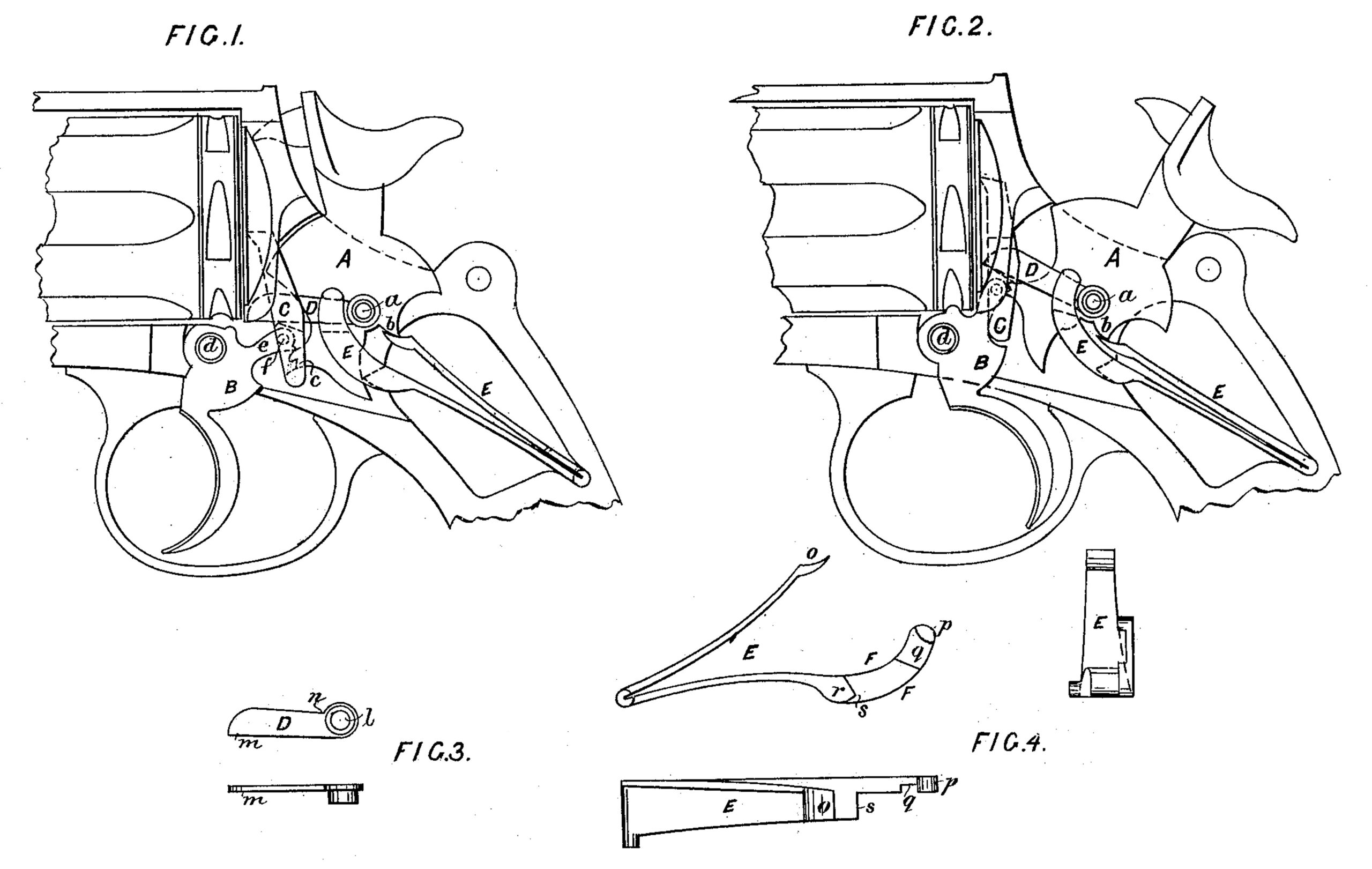
Figure 1 is a side elevation of a section of a revolver, showing all the parts of the lock in their respective places, the hammer resting in its normal position. Fig. 2 is a similar view, the hammer being at full-cock. Fig. 3 is a side view and plan of the central lever. Fig. 4 is the lock-spring inside, end, and plan view.
My present invention relates to locks for fire-arms, and is specially designed for use in revolvers, although not confined in its applicability thereto.
As indicating more particularly the nature of my invention, and in order to obviate in this instrument a detailed description of the construction and operation of certain parts of the lock, I state that the present invention is an improvement upon that for which Letters Patent of the United States were granted to me and Julien Warnant, February 18, 1879, No. 212,473. Like the aforesaid patented lock, the present one consists, if applied to revolvers, of five parts, or if used on other forms of percussion fire-arms of four, and the hammer, trigger, and pawl which I use are of the same construction and their functions are the same as those of the corresponding parts in the patient referred to.
My present improvements consist in certain features of construction of the central lever and of the lock-spring. In consequence of the simplicity of form of the central lever, it is easy to manufacture and at a greatly-lessened cost of production. The lock-spring is stronger, and, in consequence of the projection at the point producing the rebound of the hammer, possesses greater leverage for effecting the rebound. At the same time the pull of the trigger in self-cocking the weapon is equalized, permitting the use of a powerful spring, so that the force of the blow of the hammer may obviate misfires, the pressure of the pawl upon the cylinder-ratchet is modified in an important manner, the thrust of the lock-spring and reaction of the parts upon which it bears are brought into the same plane, and the return of the trigger to its normal position is sure and brisk.
In the drawings, A indicates the hammer; B, the trigger; C, the pawl; D, the central lever; E, the lock-spring; F, the arm of the lower leaf of the lock-spring.
The main frame of the weapon is provided with two pivots–the pivot a for the hammer and central lever and the pivot d for the trigger, the said trigger having a projection, e, perforated at f to receive the pivot of the pawl.
The central lever, D, is of simple construction, being a steel bar having in one end a perforation, l, whereby it is mounted upon the hammer-pivot a. The bar or central lever, D, at its projection m, rests on a shoulder or bearing in the countersunk part of the pawl and holds it in proper position. That part of the upper edge of the central lever on which the stud or lug of the arm of lock-spring bears should be very slightly above a line drawn from the bearing upon the pawl to the center of the hammer-pivot.
The lock-spring E consists of two leaves, of which the upper leaf at o bears upon the hammer at b. The lower leaf bas a projection or arm, F, countersunk at q for the passage of the lever, and is provided with a lug or stud, p, which rests on the upper edge of the central lever, D, at n, in close proximity to the front of the pivot a. The end or part r of the lower leaf of the spring I make of considerable thickness, and produce a bearing at s to engage with the tail-piece of the hammer, by means of which I obtain an increase of leverage to effect the rebound of the hammer, and am enabled to allow the two leaves of the lock-spring to be brought closely together when at full-cock, so that the spring may impart its full force to the hammer in its descent on the cartridge.
The operation of the lock is as follows: Upon cocking the weapon by the thumb the projection c of the hammer, which lies between the the lug of the pawl and the projection e of the trigger, engages with the latter, which in its upward movement carries with it the pawl and bearing is below the line joining the pivot and the central lever, D, thereby compressing the lock-spring E and effecting the rotation of the cylinder. Finally, the tooth of the trigger falls into the notch of the hammer, and the weapon is full-cocked, as shown at Fig. 2. When the trigger is retracted the hammer becomes disengaged and falls. Upon releasing the trigger the pressure of the lock-spring E, delivered through the medium of the central lever, D, acting upon the pawl, carries it downward, and with it the projection e of the trigger. Coincidently with the descent of the pawl the lower leaf of the lock-spring E descends, and its bearings, pressing upon the tail-piece of the hammer, effects the rebound of the hammer, where by its projection c is carried upward until the lug of the pawl passes it, when the pawl tilts, and its lug, coming under the projection c of the hammer, locks the hammer, as shown in Fig. 1.
The self-cocking of the weapon is effected thus: The trigger, being retracted, lifts the pawl, and the lug of the latter engages with the projection c of the hammer, which is thereby raised until the said lug passes from under the said projection, when the hammer, being released, falls. During the lifting of the pawl it engages with the ratchet and rotates the cylinder, and at the same time the pawl carries up with it the central lever, D, which compresses the lock spring E, the bearing s of the lower leaf of the said spring being then sufficiently raised, so as not to impede the fall of the hammer. After the descent of the hammer the trigger is released, when the rebound and locking of the hammer are effected, as already described.
The difference between the construction of the arm E described in Patent No. 212,473, of 1879, and the central lever, D, herein described, is very material. In the former the lock-spring the bearing upon the pawl, and the end of the arm of that spring slides upon the lug of the central piece or arm, E. In the present case the arc traversed by the point of contact of the lock-spring and the central lever, D, is so small that it may be considered equal to its chord, and the pressure of the spring is in the same plane as the points of resistance, and remains substantially constant, almost entirely obviating sliding friction and wear.
When used in a fire-arm not a revolver the pawl is a superfluity, and might be either dispensed with entirely, the central lever being made to bear directly on the trigger, or, if the self-cocking feature is desired, the pawl might be cut off just above its pivot.
What I claim as new, and desire to secure by Letters Patent, is–
1. In combination with the hammer, trigger, and pawl, a lever mounted upon the hammer-pivot and resting upon the pawl, and a main spring one arm of which engages with the hammer and the other rests upon the upper edge of the lever, whereby the latter is actuated with a thrust in a vertical plane passing through the pivot and the bearing on the pawl, as set forth.
2. In combination with the hammer, trigger, and central lever, the lock-spring having lateral stud p, adapted to rest upon the central lever, D, as set forth.
In testimony whereof I affix my signature in the presence of two witnesses.
MICHAEL KAUFMANN.
Witnesses:
WILLIAM EDWARD GEDGE,
11 Wellington Street, Strand, London, England.
LENNOX FORSTER SYKES,
Clerk to the above.