
US 337201
UNITED STATES PATENT OFFICE.
HENRY SCHLUND, OF ASTON CROSS, COUNTY OF WARWICK, ENGLAND.
REVOLVER
SPECIFICATION forming part of Letters Patent No. 337,201, dated March 2, 1886.
Application filed August 25, 1885. Serial No. 175,304. (No model.) Patented in England July 28, 1885, No. 9,081.
To all whom it may concern:
Be it known that I, HENRY SCHLUND, a citizen of England, residing at Aston Cross, in the county of Warwick, England, have invented a new and useful Improved Revolver Action, (for which I have made application for Letters Patent in Great Britain, No. 9,084, bearing date July 28, 1885,) of which the following is a specification.
My invention relates to an improved revolver-action whereby safety in locking is obtained, together with simplicity in the construction of all the parts, which are less in number than with revolvers of present construction, being such that the parts can be taken to pieces without the use of a tool, and that the hammer is entirely inclosed.
The construction will be readily understood on reference to the accompanying drawings, in which–
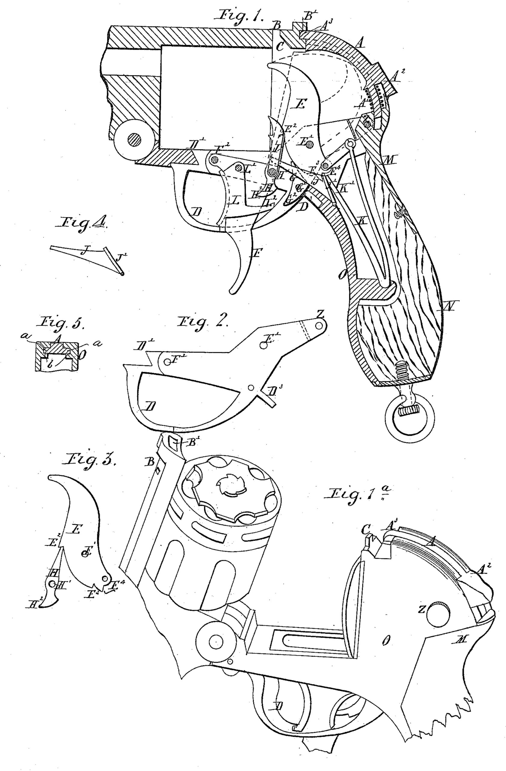
Figure 1 shows a longitudinal section of the revolver with the barrel closed. Fig.1 shows a perspective view with the barrel in the open position. Figs. 2 to 5 show detached details.
For locking the barrel a curved sliding bolt, A, having curved side flanges, a a, sliding in curved grooves b b in the framing, as shown in the section at Fig. 5, is provided, which bolt is forced forward by a spring, A, so as to enter a notch, B’, in the rib B on the barrel. This rib has a slot which in closing fits over a tongue, C, forming part of the lock. frame, so that by means of this tongue and the bolt A the barrel is securely locked in the closed position. For releasing the barrel, the bolt Alis drawn back by means of a thumb piece, A2, against the action of the spring which forces it forward again when released. The nose A3 of the bolt being suitably rounded, as shown, it will be made automatically to spring into the recess B’ when the rib is closed down again.
The trigger-guard D (shown detached at Fig. 2) is secured in position, first, by a tongue, D’, overlapping a bevel on the frame; secondly, by the part D3, fitting into a recess, and, thirdly, by a screw at Z with a milled head, so that it can be unscrewed by hand. It has pivoted to it, first, the hammer E, working on the pin E’, which is of the configuration shown in the detached view at Fig. 3; secondly, the lever F, working on the pin F’, and, thirdly, the sear G, working on the pin G’, so that on with drawing the trigger-guard, as will be presently described, all the above, named parts are removed there with. The hammer E is entirely inclosed within the handle, and is cocked by means of the lever F, which has pivoted to it by a pin at H’ the pawl H, that takes into a notch at E2 of the hammer, so that on pressing upon the lever F with the middle finger the pawl H forces back the hammer into the dotted position, in which it is held by the sear G entering the notch at E3. Upon the pin H’ is also mounted the pawl or “lifter” I, that effects the step-by-step rotation of the cylinder, and which is held up against the latter by a lever, J, acted upon by the mainspring K, and shown detached at Fig. 4. This lever at the same time presses upon a shoulder on the side of the sear, thus keeping this engaged : with the hammer.
On pressing with the forefinger against the trigger L (pivoted to the lever F at L’) for firing, the part L2 thereof acts on the tail G2 of the sear, so as to release the hammer therefrom, this being at the same time released from the pawl H by the trigger pressing upon its tail H2. The hammer is now thrown forward by the spring K, and after firing the charge is caused to rebound slightly, so as to be clear of the cylinder. This is effected by the pressure of the tail K’ of the spring upon the lever J, which in its turn presses with a rib, J’, upon the tail E4 of the hammer, so as to force it back somewhat.
For taking the action to pieces the pin Z is first unscrewed by its milled head, and the plate M, together with the stock N, is then withdrawn from the frame O. The mainspring K can then be detached from the hammer and taken out, thereby permitting, also, the removal of the lever.J. The trigger-guard D, with the before-mentioned parts attached thereto, can now be drawn out by first drawing it slightly downward, so as to release the parts D’ and D3 that are engaged with the frame, and then shifting it to the left hand somewhat. The several pins E’, F’, L’, G’, and H’ can now all be pushed out of their holes, so as to separate the parts E, F, L, G, H, and I from the trigger-guard.
Having thus described the nature of my invention and the best means I know for carrying the same into practical effect, I claim–
1. The combination, with the slotted and recessed rib B, at the rear and top of the barrel of a fire-arm, of a tongue, C, upon the frame, taking into a slot in the rib, and the curved spring-bolt A, sliding in the rear of the frame and having a nose, A3, taking into a recess if the rib, said nose being rounded, so that when the barrel is closed down the spring-bolt will be pushed back and become automatically locked with the recessed rib, substantially as described.
2. The combination of the concealed hammer E, the sear G, having a tail, G2, the pawl H, having a tail, H2, the pivoted lever F, and the trigger L, pivoted to the lever to act on the tail of the pawl, and having the projection L2, to act on the tail of the sear, substantially as described.
3. The combination, with the hinged barrel having the recess B, of the framing having curved grooves b, and the spring-bolt A, having curved flanges a, engaging the grooves, and provided with an attached finger-piece, A2, substantially as described.
4. The combination, in a revolver, of the detachable plate M, and the framing O, the stock N, and the hinged barrel, with the detachable trigger-guard D, having one end ex tending to the said plate, the screw Z, connecting the plate with the guard, the concealed hammer E, pivoted to the guard, the sear G, the pawl H, having a tail, H, and the lever F, also pivoted to the guard, and the trigger L, pivoted to said lever to operate on the tail of the pawl and having a projection, L2, to act on the sear, substantially as described.
5. The combination, in a revolver-action, the detachable trigger-guard D, the transverse screw Z, for securing the guard, the concealed hammer E, pivoted to the guard, the sear G, pawl H, having a tail, H2, and lever F, also pivoted to the guard, and the trigger L, pivoted to the lever to act on the tail of the pawl, and provided with a projection, L’, to act on the sear, substantially as described.
6. The combination, in a revolver-action, of the framing O, the hinged barrel, and the detachable plate M, with the trigger-guard D, extending inward to said plate, and the screw Z, connecting the latter to the guard, said guard having the front beveled tongue, D’, and rear stud, D3, engaging the framing, the concealed hammer E pivoted to the guard, the sear G, the lever F, and the pawl H, also pivoted to the guard, and the trigger L, pivoted to the lever to act on the pawl, and having a projection, L2, to act on the sear, substantially as described.
7. The combination, with the stock, the framing, and the barrel, of the detachable trigger-guard D, the hammer E pivoted thereto, the pawl H, sear G, and lever F, also pivoted to the guard, said pawl having a tail, H2, and the trigger I, pivoted to the lever to act on the tail of the pawl, and provided with the rearward projection L2 to act on the sear, substantially as described.
In testimony whereof I have signed my name to this specification, in the presence of two subscribing witnesses, this 11th day of August, A. D. 1885.
HENRY SCHLUND.
Witnesses:
ALFRED ROBERTS,
WALTER H. WARWICK,
Clerks to Wm. Follows, Solicitor, 40 Cherry Street, Birmingham, England.